Hierarchical Layout
The hierarchical layout style is designed to emphasize the primary direction or flow within a directed graph. The nodes of a graph are arranged into hierarchically organized layers, positioning the majority of the graph’s edges to share a common overall orientation, such as top-to-bottom. Furthermore, the order of nodes within each layer is optimized to minimize the number of edge crossings.

Note that in an acyclic graph, it is always possible to orient all edges in the same direction. Cyclic dependencies between nodes in a graph are automatically detected and resolved.
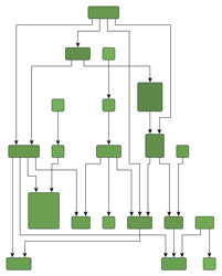
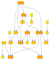
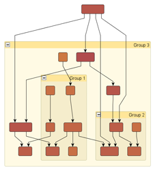
Samples of the hierarchical layout style illustrates several hierarchical layouts with a top-to-bottom orientation. The hierarchical layout style is compatible with polyline, orthogonal, octilinear, and curved edge routing. Additionally, the layout of grouped graphs is naturally supported by the hierarchical layout style.
The HierarchicalLayout class in yFiles for HTML provides a convenient way to automatically generate high-quality hierarchical layouts. It offers a range of features that influence various aspects of the layout process. HierarchicalLayout supports different predefined behaviors that you can combine and choose from. It also allows flexible customization of the layout process, if required.
Terminology
The hierarchically arranged layers, typical for this layout style (hence its name), are illustrated in Layers in the hierarchical layout style. With a top-to-bottom main direction, layers stretch horizontally and are ordered from top to bottom. Within each layer, the nodes are placed vertically and are ordered from left to right.
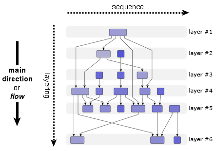
The node order within a layer is also called their sequence. The layer ordering in a diagram is also referred to as the layering. Generally, the overall orientation of the edges is the same as the main direction of the layout and is also the direction of the layering. In other words, if the main direction of the layout is right-to-left, for example, then the layering is also from right to left.
The terms layering and sequencing directly stem from the technical operation of a hierarchical layout algorithm where the layout is generated in a three-phase process:
-
Layering phase: assigns each node of the input graph to a layer.
-
Sequencing phase: finds a suitable node order within each layer (usually one that induces few crossings).
-
Drawing phase: assigns actual coordinates to the nodes and routes the edges. This phase is also known as the coordinate assignment phase.
Application Areas
The hierarchical layout style is ideal for application areas where clearly visualizing the dependency relationships between entities is crucial. In particular, if these relationships form a chain of dependencies, this layout style nicely exhibits them. Generally, whenever the direction of information flow matters, the hierarchical layout style is an invaluable tool. Moreover, this style can also be useful even when directionality is less important, as it supports a variety of advanced drawing constraints that are also valuable for other use cases.
Application areas that this layout style is suited for include, for example:
-
Workflow visualization
-
Software engineering (e.g., call graph visualization or activity diagrams)
-
Process modeling
-
Database modeling (e.g., Entity-Relationship diagrams)
-
Bioinformatics (e.g., biochemical pathways)
-
Network management
-
Decision diagrams
The following figures show sample diagrams from different application areas.
Relevant Classes
Relevant classes for this style lists the relevant classes for the hierarchical layout style.
| Phase | Class Name | Description |
|---|---|---|
Main algorithm that also provides Basic Options. |
||
Class to define supplemental Layout Data. It is used to specify more complex constraints and layout options for the individual nodes and edges. |
||
Provides node-related as well as layer-related layout options. For example, preferred minimum distances between adjacent nodes within a layer. |
||
Provides edge-related layout options. For example, different edge routing styles for different edge types. |
||
Provides options for how to treat nodes and edges in incremental mode. See From-Sketch Mode and Incremental Layout. |
||
Layering |
An implementation of this interface is responsible for assigning the nodes of a graph to layers in a hierarchical layout. In Layer Assignment Options available layering strategies for non-incremental layout calculation are presented. |
|
Enables convenient customization of the layering process where the nodes of a graph are assigned to layers in a hierarchical layout. See Layer Constraints. |
||
Sequencing |
Used to determine the order of nodes within a layer. |
|
Enables custom node order assignment within layers. See Node Order Options. |
||
Drawing |
This class is responsible for assigning each node within a layer its coordinate with respect to the node sequence. It provides several properties for obtaining more compact results, like nodeCompaction, as well as more symmetric layout results. |
|
Is used by the CoordinateAssigner to determine distances between graph elements within a layer. |
For the layering phase there are many predefined layering strategies that lead to a variety of different layout results. Instead of letting the algorithm compute the layering, some strategies also support prescribing the layering completely. Additionally, in cases where only some nodes need to fulfill specific layering requirements, the LayoutGraphLayerConstraints class can be used.
Similarly, in the sequence phase, the node orders within the layers, which are computed by DefaultSequencer, can be customized via the services provided by the LayoutGraphSequenceConstraints class.
Basic Options
- fromSketchMode
-
Enables or disables incremental layout calculation. If enabled, the algorithm considers the existing coordinates of the nodes (to learn more, please see From-Sketch Mode and Incremental Layout). You can specify which nodes are incremental using the layout data property incrementalNodes. If disabled (the default), the layout is computed from scratch (see Non-incremental Layout).
- layoutOrientation
-
Determines the main direction, or flow, that is, the overall orientation for the edges in a hierarchical layout. The layout algorithm tries to arrange nodes so that most edges point in the main direction.
By default, the overall orientation for the edges is from top to bottom. You can set the other three layout directions using the constants from the LayoutOrientation enum type. Setting a layout orientation for the hierarchical layout style shows how to set the layout direction.
const hl = new HierarchicalLayout()
// Use left-to-right main layout direction.
hl.layoutOrientation = 'left-to-right'Layout orientation sample shows one of the sample layouts for the hierarchical layout style with layout orientation left to right.
|
Note
|
The documentation for the other layout options assumes that the default orientation (top to bottom) is used. |
- stopDuration
-
Sets a time limit for HierarchicalLayout. The algorithm will stop after this time limit, even if it hasn’t reached the optimal layout. This is a soft limit, as the algorithm may exceed it slightly to finish a step.
HierarchicalLayout lets you control general drawing options such as edge routing styles or minimum distances between graph elements.
Options which affect edge routing
- routingStyleDescriptor
-
Sets the edge routing style. The default is specified by means of property defaultEdgeDescriptor.
HierarchicalLayout supports four edge routing styles:
-
orthogonal (the default)
-
polyline
-
octilinear (a variation of the orthogonal routing style)
-
curved
The following figure shows the different routing styles side by side:


const hl = getMyHierarchicalLayout()

// Switching HierarchicalLayout to polyline edge routing.
hl.defaultEdgeDescriptor.routingStyleDescriptor =
  new RoutingStyleDescriptor({
    routingStyle: 'polyline'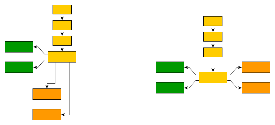
})HierarchicalLayout places the nodes to reflect the main flow of a diagram. In a top-to-bottom layout, most edges will connect to targets below their source nodes. However, this is not always possible for all edges in a diagram. Edges that connect to targets above their source nodes are backloop edges. By default, these edges exit their source nodes at the top border and enter their targets at the bottom to keep the paths short. This may reduce the readability of a hierarchical layout, as shown in the left diagram of Back-loop Routing.
Setting backloop routing will force back-loop edges to exit at the bottom and enter at the top of their source and target, respectively, emphasizing the main direction of the diagram. Back-loop routing is enabled in the right diagram of Back-loop Routing.


Options that affect the distances between elements
- minimumLayerDistance
-
The minimum distance between adjacent layers.
- nodeDistance
-
The minimum distance between two nodes in the same layer.
- edgeDistance
-
The minimum distance between two edges in the same layer.
- nodeToEdgeDistance
-
The minimum distance between a node and a non-adjacent edge in the same layer.
Distance settings in a hierarchical layout illustrates where the settings for the drawing options take effect in a diagram.
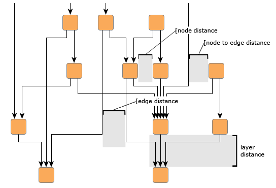
Note that the distance settings between edges and also between edges and nodes only take effect on edges that span at least one layer in the diagram. Also, keep in mind that all distances are only minimum distances. The layout algorithm may use larger distances than specified to achieve a more visually appealing result.
HierarchicalLayout provides additional support to fine-tune distances between graph elements, considering the thickness of edges. This is especially useful for Sankey diagrams; see the Sankey Diagram Demo for an example. To specify each edge’s thickness, use the layout data property edgeThickness.
Further node- and edge-related options
- HierarchicalLayoutNodeDescriptor
-
HierarchicalLayoutNodeDescriptor can be used to configure node-related layout and drawing options. For example, you can set the relative alignment of nodes within their layer or the preferred minimum distance from obstacles. The descriptor instance can be specified individually for single nodes by means of the layout data property nodeDescriptors. If an individual descriptor for a node is not specified, the defaultNodeDescriptor will be used.
- HierarchicalLayoutEdgeDescriptor
-
HierarchicalLayoutEdgeDescriptor can be used to configure edge-related layout and drawing options. For example, you can set different routing styles for edges or the minimum length of the first and last edge segments. The descriptor instance can be specified individually for single edges by means of property edgeDescriptors. If an individual descriptor for an edge is not specified, the defaultEdgeDescriptor will be used.
Labeling
Integrated edge labeling is one of the two scenarios for placing the edge labels of a graph. It refers to the support provided by HierarchicalLayout for finding optimal placements for edge labels such that edge labels do not overlap with each other or with other graph elements.
Integrated labeling can be enabled or disabled using the following property:
- edgeLabelPlacement
-
Determines how the layout handles the placement of edge labels. Setting the property to value Integrated enables integrated labeling.
The before/after pair in the following figure shows the result of a hierarchical layout with integrated edge labeling.


|
Tip
|
Optimal label placement with integrated labeling can be achieved using FreeEdgeLabelModel as the label model for the edges. As explained in Label Models, this edge label model is ideally suited for integrated labeling and yields the best match for a label location that is computed by HierarchicalLayout. |
The HierarchicalLayout class can also handle node labels, see property nodeLabelPlacement. When specifying value Consider, the node labels keep their relative position to their associated node, and the label is considered during the processing, specifically the routing, of adjacent graph elements. This guarantees that they will not overlap nodes or other graph elements in the diagram.
- nodeLabelPlacement
-
Specifies how the algorithm handles the placement of node labels.
Grouped Graphs
The HierarchicalLayout fully supports the layout of grouped graphs. The algorithm calculates both the position and dimension of group nodes. This section describes several group-related settings that can significantly influence the layout results.
HierarchicalLayout offers different layer assignment policies for grouped graphs that can be specified with the property groupLayeringPolicy:
-
Ignore Groups: nodes are assigned to layers regardless of the grouping hierarchy.
-
Recursive: the layer assignment is computed by recursively traversing the grouping hierarchy in a bottom-up fashion (starting with the leaves in the hierarchy tree) and calculating the layers independently for the children of each group (default behavior).
-
Recursive Compact: the same as "`Recursive`," but an additional post-processing step is applied to reduce the overall number of layers within groups.
Group-ignoring vs. recursive layer assignment compares the layer assignment policies. When ignoring groups, layering of grouped nodes can be influenced by nodes outside the group node (in the same way as if there are no groups at all). In contrast, when using a recursive layer assignment, grouped nodes are processed without interference from nodes outside the group.


For the layer alignment policy RECURSIVE, groups and normal nodes may occupy the same layer. The property groupAlignmentPolicy can be used to specify how “ordinary” nodes that are in a layer with group nodes are placed relative to these group nodes. In the above figure, “Recursive layer assignment policy”, the group alignment is TOP.
|
Important
|
HierarchicalLayout’s support for grouped graphs currently does not include the following features for edge ends that directly connect to group nodes: fixed port candidates, and edge/port grouping (bus-style edge routing). |
HierarchicalLayout’s support for incrementally calculating layouts of grouped graphs enables smooth transitions when realizing collapsing and expanding of group nodes. Incremental hierarchical layout when group nodes are collapsed and expanded presents the results of both these operations. The resulting folder node and group node, respectively, are incrementally inserted into the existing layout.


Incremental hierarchical layout of graphs with grouped nodes is shown in the demo application Hierarchical Nesting Demo.
Recursive Edges Routing
To achieve more stable results when collapsing and expanding group nodes in interactive scenarios with incremental mode enabled, HierarchicalLayout supports different routing styles for recursive edges.
Recursive edges connect nodes that belong to different group nodes. These edges are configured to connect to the group nodes only at the top or bottom side.
The recursiveEdgePolicy property in class HierarchicalLayoutEdgeDescriptor sets the routing style for a recursive edge. The following routing styles are available:
- DIRECTED
-
At their source end, recursive edges exit the containing group node(s) at the bottom side; at their target end, they enter the containing group node(s) at the top side.
- UNDIRECTED
-
At both ends, recursive edges exit/enter the containing group node(s) at the bottom side or top side.
- OFF
-
Recursive edges are not routed in a specific way. At both ends, they can exit/enter the containing group node(s) on the left or right side to connect as directly as possible.
The following figure illustrates the different routing policies for recursive edges:


Recursive edges provide more stable results when collapsing/expanding group nodes in incremental mode because their exiting/entering sides in group nodes remain unchanged.
To further improve the results and preserve as much as possible from the existing drawing, the following can be applied in combination with recursive edges:
-
groupLayeringPolicy should be set to a recursive policy.
-
When expanding/collapsing a group node, the original size of the group (before expanding/collapsing) should be assigned using alternativeGroupBounds.
-
The alternative path of specific edges should be assigned to alternativeEdgePaths as follows:
-
Collapsing: For edges that are incident to the group node itself and edges for which either the source or target is inside the group node, the path
beforecollapsing the group node has to be assigned as the alternative path. If the source and target are either both inside or both outside the group node, no alternative path is required. -
Expanding: For edges that are incident to the collapsed group node, the path
beforeexpanding the group node has to be assigned as the alternative path.
-
-
Folder nodes, i.e., collapsed group nodes, should also be marked using folderNodes.
Note that the following features are not supported for recursive edges:
-
Sequence constraints are not supported for recursive edge routing policies DIRECTED and UNDIRECTED. Also, any edge sequence constraint information will be ignored for such edges.
-
Edge grouping is not supported for recursive edge routing policies DIRECTED and UNDIRECTED. Also, any edge grouping information will be ignored, including automatic edge groupings.
-
If direct routing between groups and their content for an edge is enabled, the edge may not be strictly recursive but may exit/enter group nodes at the left or right side.
-
Back-loop routing is ignored for edges with recursive edge routing policy DIRECTED and UNDIRECTED, including edges where the source or target are not inside a group node.
Non-incremental Layout
By default, a HierarchicalLayout instance operates in non-incremental layout mode. This means that it recomputes the entire layout of a given graph. This behavior aligns with that of the other major layout algorithms in yFiles for HTML. The non-incremental hierarchical layout is also referred to as a layout from scratch.
In the general three-phase process of generating a hierarchical layout, the first phase, which assigns the nodes of a graph to different layers:
-
Offers a variety of predefined layering strategies.
-
Supports custom layering requirements that are not covered by these strategies through Layer Constraints.
The second phase, responsible for finding a good ordering of the nodes in each layer, supports a similar scheme to achieve custom sequencing requirements not covered by the default behavior.
Layer Assignment Options
HierarchicalLayout assigns the nodes of a graph to separate layers using an ILayerAssigner implementation. Layers are ordered and, assuming a top-to-bottom orientation for the main flow, are arranged vertically from top to bottom (see also Layers in the hierarchical layout style).
The layer order is a 1-based index for the layers that also denotes the so-called rank of all nodes assigned to a layer. Note that the rank of a node is important in conjunction with some of the layer assigner implementations.
From-Scratch Layering Strategy
The layering strategy in non-incremental layout mode can be set using the fromScratchLayeringStrategy property. According to the layering strategy constant from the HierarchicalLayoutLayeringStrategy enum type, the actual ILayerAssigner implementation is chosen. Internally, HierarchicalLayout also sets up any specific configuration of the ILayerAssigner if necessary.
|
Note
|
When fromSketchMode is active, this strategy will have no effect. |
The following layering strategy constants are available:
- HIERARCHICAL_TOPMOST
-
A simple hierarchical layering variant. All nodes without incoming edges (indegree zero) will be assigned to the topmost layer of the layout. The number of separate layers will be as small as possible. Uses TopologicalLayerAssigner with ranking policy
NONE. - HIERARCHICAL_OPTIMAL
-
An optimal hierarchical layering strategy. The layer distance of an edge is the absolute difference between the layer numbers (ranks) of its source and target node. Layer assignment will be done in such a way that the overall sum of the layer distances of all edges in the layout is minimal. Uses WeightedLayerAssigner.
- HIERARCHICAL_TIGHT_TREE
-
A good heuristic that approximates the layering done by Hierarchical — Optimal. Uses TopologicalLayerAssigner with ranking policy
TIGHT_TREE. - HIERARCHICAL_DOWNSHIFT
-
An even faster heuristic that approximates the ranking done by Hierarchical — Optimal by down-shifting some nodes in the layering. The quality is usually worse than the one produced by Tight Tree Heuristic. Uses TopologicalLayerAssigner with ranking policy
DOWN_SHIFT. - BFS
-
Layering based on a breadth-first search (BFS). All edges will span at most one layer in the resulting drawing. Edges between nodes that belong to the same layer are possible. To specify nodes that should be placed into the first layer, specify supplemental layout data accordingly. Note that in the absence of such data all nodes that have no incoming edges (indegree zero) are placed into the first layer. Uses BfsLayerAssigner.
- FROM_SKETCH
-
Layer assignment strategy that uses the initial y coordinates of the nodes to determine a layering. It tries to find a layering that is similar to the one in the input graph. When this layering strategy is used, the layout algorithm may place nodes in the same layer, even though they are connected by an edge. These inner layer edges are always routed in an orthogonal style. Uses FromSketchLayerAssigner.
- USER_DEFINED
-
The ranks of the nodes will be given by the user. To specify the ranks, configure supplemental layout data accordingly. Uses GivenLayersAssigner.
Except when using one of the latter three layering strategies, the nodes of a graph are assigned to layers such that edges of the graph will, as much as possible, have the same overall orientation. With the From-Sketch and User-defined Layering strategies, the layering is prescribed by some external means, and there cannot be much said about the direction of the edges.
Using either the From-Sketch or User-defined Layering strategies, it is possible to specify the exact layering for all nodes of a graph. In cases where only a few nodes need to fulfill specific layering requirements, adding layer constraints may be the better option.
|
Note
|
When undirected edges need to be taken into account during layer assignment, then any layering strategy specified as outlined above is ignored and instead the ConstraintIncrementalLayerAssigner is used. |
Node Order Options
In a hierarchical layout, the order of nodes within a layer affects the number of edge crossings in the final layout. By default, HierarchicalLayout uses class DefaultSequencer to determine this node order. You can customize the generated sequencing using the features described in Sequence Constraints.
From-Sketch Mode and Incremental Layout
By default, HierarchicalLayout does not consider the arrangement of the input graph, instead recalculating the layout of the entire graph from scratch. This is appropriate for static graphs but not ideal when you want to preserve parts of an existing layout.
For scenarios where you need to maintain portions of your graph while adding or rearranging other parts, you can enable from-sketch mode via property fromSketchMode. This mode treats the existing graph arrangement as a sketch that defines both the starting point and the desired structural characteristics of the resulting layout.
Incremental and Sketch-Based Elements
When from-sketch mode is active, you control how each element is treated by marking it as either incremental or sketch-based. The algorithm then integrates the incremental elements into the existing layout structure while preserving sketch-based elements.
- Incremental elements
-
Elements that are newly added or whose input coordinates should be ignored. The algorithm computes their layers and positions.
- Sketch-based elements
-
Elements whose input positions should influence the result. The algorithm preserves them according to their so-called incremental hint.
A hint specifies how a node or edge is handled in from-sketch mode, e.g., to what degree a node’s position should be preserved.
|
Note
|
If from-sketch mode is enabled but no hints are explicitly specified, all nodes and edges automatically receive the default sketch-based hint (FROM_SKETCH for nodes, KEEP_RELATIVE_ORDER for edges). This preserves the relative structure of the entire graph without fixing any absolute coordinates. |
Sketch-based elements can be assigned different hints that control how strictly their positions are preserved:
- Relative positioning (default)
-
Hints KEEP_RELATIVE_ORDER and FROM_SKETCH maintain the relative order of elements within and across layers. The algorithm may adjust absolute coordinates to accommodate incremental elements or satisfy spacing constraints, but the spatial relationships remain stable.
- Exact positioning
-
The EXACT_COORDINATES hint attempts to preserve precise input coordinates. Adjustments may still occur to ensure valid spacing unless explicitly configured to allow distance violations.
A complete overview of available hints and their behavior is provided in Advanced Usage: Fine-Grained Incremental Hints.
Use Cases
From-sketch mode supports a wide variety of use cases. Two typical scenarios are discussed below.
- Interactive Graph Creation
-
When building graphs interactively, you typically want each newly added element to integrate smoothly into the existing layout without disrupting what’s already there. From-sketch mode enables this by treating the current layout as the sketch and the new elements as incremental additions.
- Targeted Layout Refinement
-
When you have an existing graph with only a small portion requiring adjustment, recomputing the entire layout is unnecessarily disruptive. By only marking specific subgraphs as incremental, it is possible to rearrange only those elements while the rest of the graph remains stable.
Interactive Construction Example
Progressive graph creation demonstrates interactive graph creation. Starting with an initial diagram, new nodes and edges (highlighted in color) are progressively added. Each layout calculation treats the previous result as the sketch, integrating new elements with minimal changes to the existing drawing.


Targeted Refinement Example
Rearranging a subgraph while preserving the overall layout shows targeted refinement in action. A subgraph (highlighted in the left image) is marked as incremental. The subgraph is rearranged and integrated in the surrounding existing drawing.


Specifying Incremental Elements
For common scenarios where you’re adding new elements to an existing layout, use the layout data properties incrementalNodes and incrementalEdges. Elements not explicitly marked as incremental are automatically treated as sketch-based.
const graph = getMyGraph()

// Get a collection of nodes that should be processed using incremental layout semantics.
const incrementalNodes = myGetIncrementalNodes()

// Get a collection of edges that should be considered incremental (full rerouting).
const incrementalEdges = myGetIncrementalEdges()

// Create the layout, enabling the from-sketch mode
const hl = new HierarchicalLayout({
  fromSketchMode: true
})
// Create the layout data
const layoutData = new HierarchicalLayoutData()

// Set the incremental item collection on it.
// There are other ways to define the incremental hints, not
// using a collection. For example, you could specify a function that creates
// the incremental hints for each item on the fly. But in this example we
// simply use a collection.
layoutData.incrementalNodes = incrementalNodes
layoutData.incrementalEdges = incrementalEdges

// Apply the layout
graph.applyLayout(hl, layoutData)|
Note
|
Nodes marked as incremental using incrementalNodes receive the INCREMENTAL hint, while the other nodes receive the default hint FROM_SKETCH. See the following section for more details. |
Advanced Usage: Fine-Grained Incremental Hints
For more control over how nodes integrate into your layout, you can assign specific incremental hints using incrementalNodeHints. These hints allow you to balance between free arrangement and sketch-based positioning.
Node Hints
- INCREMENTAL
-
The algorithm freely determines both the layer and the position within that layer. This is the hint applied when using the incrementalNodes collection.
Use this when: Adding completely new nodes that have no meaningful position in the sketch. - INCREMENTAL_WITH_LAYERS_FROM_SKETCH
-
The node stays in its current layer (determined from its sketch coordinates), but the algorithm freely chooses its position within that layer.
Use this when: You want to maintain the hierarchical layer of a node but allow reordering within that layer. - KEEP_RELATIVE_ORDER
-
The node maintains its relative position to other sketch-based nodes, both within its layer and across layers. This is the default for nodes not explicitly mapped with any other hint.
Use this when: You want to preserve the existing relative layering and the ordering within the layers. Enabling only the fromSketchMode and not defining any other hints means that all nodes get this hint. - FROM_SKETCH
-
Like KEEP_RELATIVE_ORDER, but additionally preserves visual shapes and relationships such as left-of/right-of relations with other sketch-based nodes, even if they are not on the same layer.
Use this when: You want stronger preservation of the sketch layout. - EXACT_COORDINATES
-
The node stays as close as possible to its exact input coordinates, both for layer assignment and position within the layer. The algorithm may still move the node to satisfy minimum distance constraints or avoid overlaps. Can be customized using factory method createExactCoordinatesHint, making it possible to allow distance violations or overlaps.
Use this when: Specific node positions are critical and should be disturbed as little as possible.
|
Important
|
Exact coordinates in the layer direction (y-coordinate for top-to-bottom layouts, x-coordinate for left-to-right layouts) are more challenging to maintain compared to coordinates in the sequence direction (x-coordinate for top-to-bottom layouts, y-coordinate for left-to-right layouts). Generally, exact coordinates may lead to suboptimal layouts with increased edge crossings or bends, since keeping coordinates restricts other optimization steps. |
- INCREMENTAL_GROUP
-
Specific hint for group nodes only. The group node is placed incrementally as a whole unit. Descendants of the group maintain their relative positions within the group but not relative to elements outside the group.
Use this when: Inserting an entire grouped subgraph that has its own internal structure you want to preserve.
Edge Hints
- INCREMENTAL
-
The edge is freely rerouted to find an optimal path through the layers. This is automatically applied to edges incident to incremental nodes.
Use this when: The edge is newly added, or you want to optimize its routing. - KEEP_RELATIVE_ORDER
-
The edge maintains its relative position as it passes through layers. For example, if an edge currently passes to the right of certain nodes, it will continue to do so. This is the default for edges between sketch-based nodes. Note that this hint only affects edges where both endpoints are sketch-based nodes. Edges incident to incremental nodes are always routed incrementally.
Use this when: You want to preserve the routing character of existing edges.
Specifying Fine-Grained Node Hints
The following code snippet shows how different node hints are specified via layout data.
const graph = getMyGraph()

// Create the layout, enabling the from-sketch mode
const hl = new HierarchicalLayout({
  fromSketchMode: true
})

// Create the layout data to define custom incremental hints
const layoutData = new HierarchicalLayoutData()

// Get a collection of nodes that should be processed using incremental layout semantics
const incrementalNodes = myGetIncrementalNodes()

// Define hints for nodes using a predicate function
layoutData.incrementalNodeHints.mapperFunction = (node) => {
  if (incrementalNodes.includes(node)) {
    // A node in the collection is incremental
    return IncrementalNodeHint.INCREMENTAL
  }
  if (node.tag === 'MyExactCoordinateNode') {
    // If a node has some custom tag, define that it should preserve its current exact coordinate
    return IncrementalNodeHint.EXACT_COORDINATES
  }
  // Sketch-based behavior that does not preserve coordinates for all other nodes
  return IncrementalNodeHint.FROM_SKETCH
}

// Apply the layout with the layout data
graph.applyLayout(hl, layoutData)When inserting nodes or routing edges according to their hint, nodes and edges that have no hint associated retain their original relative order both within layers and from layer to layer.
The incremental layout capabilities of the HierarchicalLayout are also shown in the Interactive Hierarchical Layout Demo and Incremental Hierarchical Layout Demo.
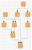
Example: Effect of Different Node Hints
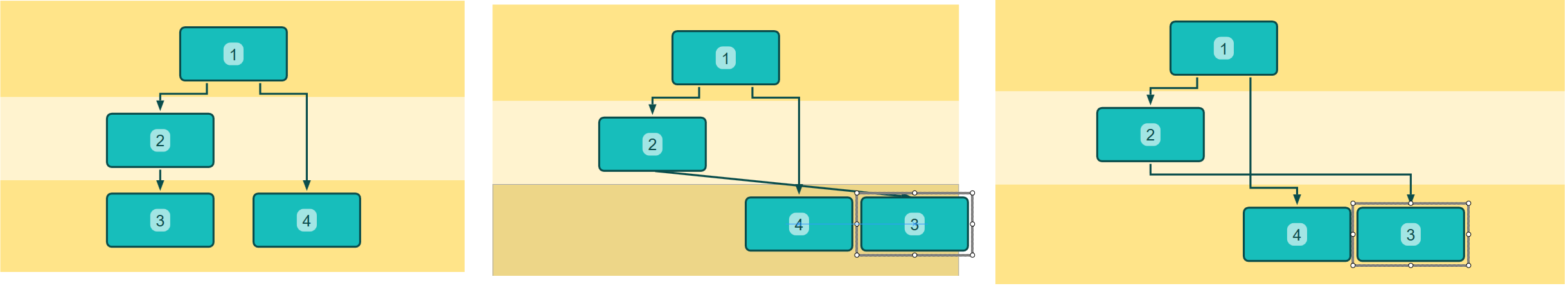
In the following interactive editing scenario, node "3" is dragged to the right. The layout is then recalculated with all nodes receiving hints as indicated below. Note that edges are always rerouted (incremental hint) in this example.
For each hint configuration, three states are shown in three panels from left to right: the initial layout, the sketch after dragging node "3", and the final layout result.
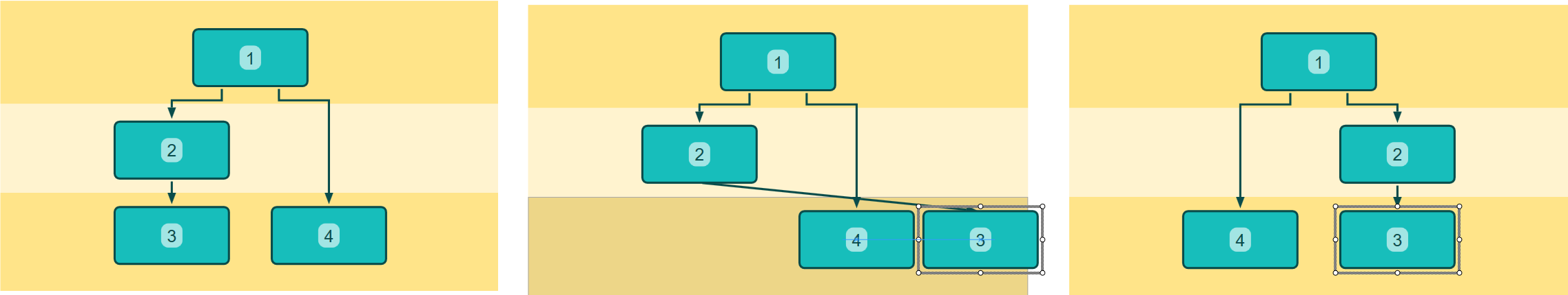
Observe that the relative order of "3" and "4" is kept as indicated by the sketch after the drag. The coordinates are adjusted to create a clean layout while maintaining only the layering and intra-sequence ordering.
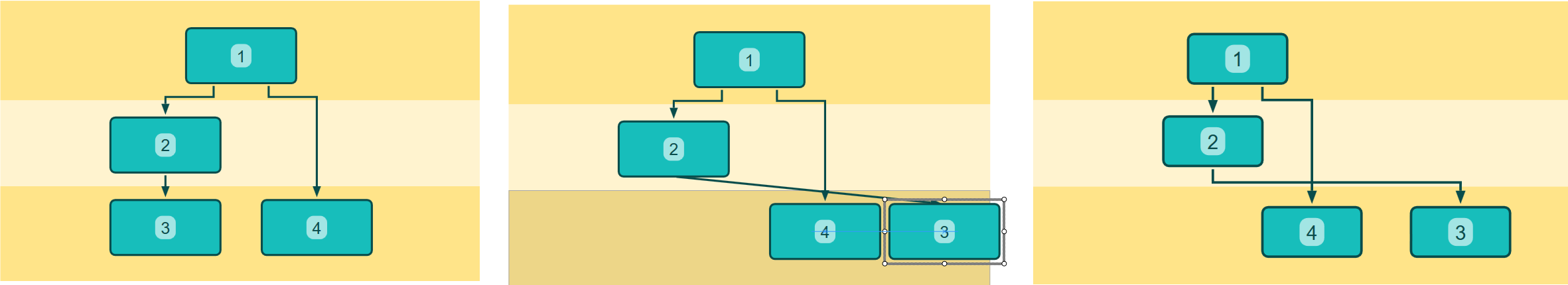
Nodes "3" and "4" keep the order as before, and additionally, node "4" is not allowed to change its "right-of" relation with node "2" on the previous layer. The shape of the sketch remains intact.
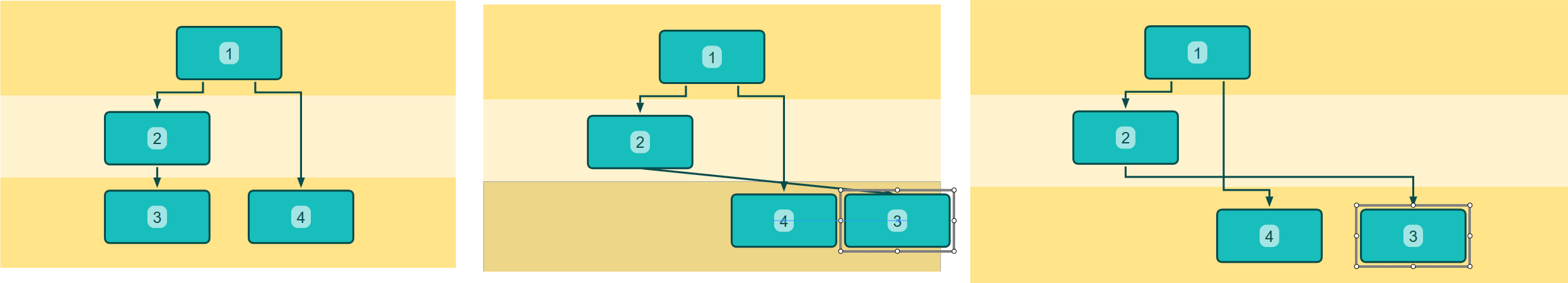
Now, not only is the relative order maintained, but the exact coordinates of all nodes are preserved, except for node "3", which is moved slightly to satisfy the minimum distance constraint to node "4".
With a hint created via createExactCoordinatesHint that allows distance violations, nodes "3" and "4" retain their exact coordinates despite being closer than the minimum distance.
Related Demos
For interactive examples of from-sketch mode and incremental layout:
-
Incremental Hierarchical Layout Demo. Shows interactive graph creation and editing using different hint configurations.
-
Hierarchical Nesting Demo: Demonstrates incremental layout applied when folding and expanding group nodes.
Layer Constraints
HierarchicalLayout supports user-defined layer constraints for both from-scratch layout mode and for incrementally inserted graph elements in incremental layout mode. Nodes can be restricted to be placed:
-
absolutely, i.e., into the first or last layer of the layout, or
-
relatively, i.e., relative to a given reference node in the same layer, in a layer preceding that of the reference node, or in a layer following that of the reference node.
The nodes that have no constraints defined, are processed using the layer assignment strategy that is set with HierarchicalLayout.
|
Note
|
Relative layer constraints with enabled fromSketchMode can also be specified between sketch-based nodes and incremental nodes. Relative constraints between two sketch-based nodes are ignored. |
Constrained hierarchical layering shows a resulting hierarchical layout where nodes with an absolute constraint are placed in the topmost layer (note the color emphasis on these nodes). Normally, i.e., when no constraints are specified, these nodes are placed in the very center of the graph, as can be observed in the original hierarchical layout.


HierarchicalLayoutData<TNode, TEdge, TNodeEdge, TNodeLabel, TEdgeLabel>.layerConstraints returns an instance of LayerConstraintData<TNode> which provides the following methods to define both absolute and relative layer constraints for nodes.
- placeAtTop(node: TNode, priority: number): void
- placeAtBottom(node: TNode, priority: number): void
-
Absolute constraints.
- placeInSameLayer(referenceNode: TNode, sameLayerNode: TNode, priority: number): void
- placeInOrder(upperNode: TNode, lowerNode: TNode, minimumDistance: number, weight: number, priority: number): void
-
Relative placement constraints for two nodes.
The following code example shows how to specify constraints for two nodes.
const hierarchicalLayoutData = new HierarchicalLayoutData()
const layerData = hierarchicalLayoutData.layerConstraints
// place node1 in the top layer
layerData.placeAtTop(node1)
// place node2 in a layer below node1
layerData.placeInOrder(node1, node2)The methods for defining relative constraints optionally support specifying a minimum distance to the other node, as well as a priority value for the constraint. A constraint’s priority is a positive integer value used to resolve conflicting constraint definitions by ignoring low-priority constraints.
Sequence Constraints
Sequence constraints enable you to define a specific order for nodes within a layer. Nodes can be constrained to be placed:
-
absolutely, i.e., at the beginning or at the end of their layer, or
-
relatively, before or after a given reference node.
Any remaining nodes without defined constraints are placed by the algorithm at optimal positions within their respective layer. Specifically, for a set of nodes {A, B, C} within a layer where relative constraints specify a sequence like this: {A before B, B before C}, other nodes from the layer might still appear within the sequence in the resulting layout.
Absolute sequence constraints shows an example with absolute constraints. Nodes with an absolute "place-at-head" constraint are placed at the beginning of their respective layers (note the visual emphasis on these nodes). Normally, i.e., when no constraints are specified, these nodes are placed in the very center of the graph, as shown in the original hierarchical layout.


The following figure shows an example with relative constraints for nodes within their layer.


HierarchicalLayoutData<TNode, TEdge, TNodeEdge, TNodeLabel, TEdgeLabel>.sequenceConstraints allows you to conveniently define both absolute and relative node order constraints. It returns an instance of SequenceConstraintData<TNode,TEdge,TItem> which provides the following methods to specify node order constraints:
- placeNodeAtHead(node: TNode): void
- placeNodeAtTail(node: TNode): void
-
Absolute constraints
- placeNodeBeforeNode(beforeNode: TNode, afterNode: TNode): void
-
Constraints relative to a given reference item
Specifying sequence constraints shows how sequence constraints can be specified for given nodes
const hierarchicalLayoutData = new HierarchicalLayoutData()
const sequenceData = hierarchicalLayoutData.sequenceConstraints
// place node1 first
sequenceData.placeNodeAtHead(node1)
// place node2 after node1
sequenceData.placeNodeBeforeNode(node1, node2)Layer Assignment with Undirected Edges
To determine the layering for the nodes of a graph, the layer assignment phase by default considers the directedness of all edges in the graph. The hierarchical layout style arranges the nodes of a graph such that the (majority of) edges have the same overall orientation in the resulting diagram (for example, top-to-bottom).
With support for undirected edges, HierarchicalLayout lets you specify that a given edge in the resulting diagram should neither be oriented with nor against the main direction. Instead, its nodes should preferably be placed in the same layer. Note that due to other optimization criteria, this placement cannot always be guaranteed (see also the tip below).
Generally, this feature allows you to specify that a subset of edges should be considered irrelevant for the actual hierarchical structure of a diagram. It is especially suited to achieve aesthetic layouts for diagrams where nodes have an attached non-structural element that is exclusively connected to them, such as 'note' or 'description' nodes in UML diagrams.


Edges can be marked as undirected using the layout data property edgeDirectedness, which holds a floating-point value per edge to specify the edge’s directedness. An edge can be marked using one of the following directedness values:
-
0 denotes an undirected edge; the algorithm tries to place the nodes connected by this edge into the same layer, if possible.
-
1 denotes a regular edge that should be oriented with the main direction of the resulting hierarchical layout.
-
-1 denotes an edge that should be oriented against the main direction of the resulting hierarchical layout.
By default, all edges are assumed to have a directedness value of 1.
|
Tip
|
To achieve a specific subset of edges that points against the main direction in the resulting diagram, it can be faster to explicitly revert these edges before the layout invocation and restore their original direction afterward. This can be conveniently done with the help of layout stage ReverseEdgesStage. Relative layer constraints can be used to fix an edge so that its nodes are always placed into the same layer. |
Custom Subcomponents
HierarchicalLayout allows you to define subcomponents. Subcomponents are subsets of nodes from the input graph that will be arranged using a specified ILayoutAlgorithm instance. This means different components of the same graph can be handled by different layout algorithms while the components on the top level are arranged in the usual hierarchical way. Note that components cannot be nested.
Example
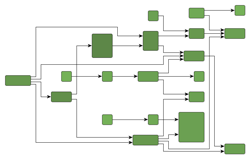
In Layout with three subcomponents, a possible use case is illustrated. The example graph contains three different subcomponents, indicated by node labels. Nodes that do not belong to any component are not labeled. The main hierarchical layout has a top-to-bottom orientation and uses orthogonal edge routes. The first subcomponent ('HL' labels) is also arranged by a hierarchical layout algorithm, but with a left-to-right orientation and polyline edge routes. The 'Tree' component is arranged by a tree layout algorithm. Finally, the last component is handled by the organic layout algorithm ('O' labels).

Usage
The behavior of subcomponents is defined by their associated HierarchicalLayoutSubcomponentDescriptor. Set the layout algorithm that should be applied to the associated subcomponent using the layoutAlgorithm property. Additionally, some components can be integrated into the surrounding hierarchical layout for a better fit. The policy determining whether to integrate a subcomponent in this way can be specified with the property placementPolicy.
To define subcomponents, use the layout data property subcomponents. The add method of the property takes the subcomponent descriptor as a parameter to create a new component that should be arranged according to the specifications in the descriptor. The returned item collection allows conveniently defining which nodes should belong to the newly added subcomponent. See the following code example that shows how to define a subcomponent that should be arranged by an organic layout algorithm.
const graph = getMyGraph()
const hl = getMyHierarchicalLayout()
const hlData = new HierarchicalLayoutData()

// Create a subcomponent descriptor which specifies how the subcomponent is handled
const descriptor = new HierarchicalLayoutSubcomponentDescriptor()
// The subcomponent will be arranged by the provided OrganicLayout instance
descriptor.layoutAlgorithm = new OrganicLayout()

// Retrieve an ItemCollection<INode> which defines all nodes of a subcomponent
const organicSubset = hlData.subcomponents.add(descriptor)

// Assign the nodes to the organic subcomponent by using an Array<INode>
organicSubset.items = getMySubcomponentNodes()

// Apply the hierarchical layout with the defined subcomponents
graph.applyLayout(hl, hlData)Inter-Edges
Edges that connect nodes of different subcomponents, or nodes of a subcomponent with top-level nodes, are called inter-edges.
There are a few minor restrictions regarding inter-edges. Their style might differ slightly from normal hierarchical edges. Additionally, the minimum first/last segment length setting might not always be satisfied for inter-edges.
Grouped Graphs
Subcomponents can be defined for grouped graphs. However, there are some restrictions:
-
If the group node itself is not part of the subcomponent, all subcomponent nodes must be on the same hierarchy level.
-
If a group is assigned to a subcomponent, all its descendants (including other group nodes) must also be in the same component.
Subcomponent Placement
Subcomponents are generally handled by the hierarchical layout as if they were a single large node. For subcomponents that are only connected to the remaining graph by a single node outside the component (also called a connector node), it is possible to integrate the component layout into the hierarchical layout. If the placementPolicy allows for integrated placement of the component, the connector node and all inter-edges are included in the layout calculation for the component. This way, subcomponents that are associated with a unique connector node will be placed in direct proximity to the node by the hierarchical layout. The available placement policies are:
- ISOLATED
-
If this placement policy is selected for a subcomponent, it is handled as a large, independent node by the hierarchical layout, even if there is a connector node at which the component could be integrated.
- ALWAYS_INTEGRATED
-
If this placement policy is selected, the subcomponent will always be integrated into the HierarchicalLayout, unless there is no connector node at which to integrate it. The algorithm will allow overlaps with the rest of the graph or deviations from the specified edge routing behavior to integrate the component. This policy is most effective when the resulting component layout is predictable and unlikely to cause such problems.
- AUTOMATIC
-
This is the default policy. If this policy is selected for a subcomponent that has a connector node, the algorithm will check whether the integrated component layout is desirable in the context of the HierarchicalLayout. It ensures that the component layout does not cause overlaps, is compatible with the specified edge routing behavior, and has no constraints that directly prevent it from being placed at the connector node. Some important criteria that should be considered:
-
The sub-layout must have an orientation/direction that is orthogonal with respect to the main hierarchical layout orientation. Consider the top-to-bottom orientation as the main direction: the sub-layout must be completely left or right of the owner node. The inter-edges of the owner must connect left or right.
-
If in incremental layout mode, the sketch of the component must comply with the location of the component layout in relation to the owner node.
-
Layer constraints with the connector node must allow that the connector can be in the same layer as the subcomponent.
-
Any sequence constraint with the connector node must comply with the subcomponent layout (e.g., a place-before constraint complies with a subcomponent layout where all the component nodes are placed before the connector node).
-
|
Tip
|
Integrated subcomponents work especially well when the inner sub-layout algorithm has an explicit layout orientation (like e.g. HierarchicalLayout or TreeLayout). |
Using Placement to Improve Component Alignment
In some use-cases, subcomponents may have a single node connecting to the rest of the graph that lies in the component. In such cases, it often makes semantic sense to align that node with graph nodes outside the component, that are placed in the same layer by the hierarchical layout. Since the HierarchicalLayout considers the component as a single large node, this cannot be guaranteed implicitly. However, the integrated placement can be used to achieve the desired alignment by excluding that specific node from the subcomponent.
Port Candidates
The HierarchicalLayout offers extensive support for handling ports as described in Port Placement. It allows restricting port locations with port candidates for edges as well as nodes, and also provides sophisticated support for matching these candidates.
|
Note
|
For edges incident to group nodes, the HierarchicalLayout class only considers free port candidates. Furthermore, node port candidates for groups are not supported. |
Edge Grouping
The hierarchical layout algorithm supports grouping multiple edge ends to be anchored at the same location. You can specify this for both source and target ends. The concept of edge grouping and its setup are described in Edge and Port Grouping.
Edges that belong to the same group at a specific end will be routed in a bus-like style. If multiple edges start or end at nodes in the same layer and belong to the same group, they will be merged into a bus structure in that layer. This happens even if they do not share the same node at their ends.
HierarchicalLayout supports both automatic and custom edge grouping.
Automatic Edge Grouping
Automatic edge grouping is disabled by default. You can enable it using the following property:
- automaticEdgeGrouping
-
Enables/Disables automatic edge grouping
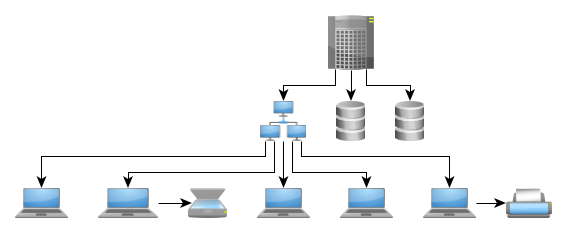
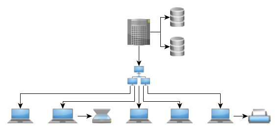
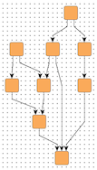
Automatic edge grouping attempts to group as many edges as possible without changing the graph’s meaning. Edges are grouped either at a common source node or at a common target node. They will not be grouped if doing so would create ambiguous paths. Automatic Edge Grouping illustrates the effect of automatic edge grouping. Note that edges with a common source are grouped, as well as edges with a common target. Also, note that the outgoing edges at node B are not grouped because grouping them at this node would imply a connection between A and D.


Edges are only grouped at their source (target) node if they do not have port candidates at that node. Also, edges cannot be grouped at a node with specified port candidates. If automatic edge grouping is enabled, any user-specified edge groups are ignored.
Custom Edge Grouping
If more flexibility is needed, edges can be grouped manually using the layout data properties sourceGroupIds and targetGroupIds, respectively. Edges which share the same group identifier are considered to belong to the same edge group.
The general rule describing how edge grouping structures are created can be summarized as follows: edge paths are merged from both the source and target sides, beginning as close to the respective edge ends as possible. From this rule, the following consequences arise:
-
Edges that start at a common node and belong to the same source group (i.e., are associated with the same source group identifier) are merged together such that they are anchored at the same location. The same holds true for edges ending at a common node that belong to the same target group.
-
Edges that start at nodes in different layers but belong to the same source group are merged together in a cascading manner. The same holds true for edges ending at nodes in different layers but belong to the same target group.
From this rule, it is also clear that edges being grouped at both ends will result in edge routings where the paths are merged to the maximum extent possible.
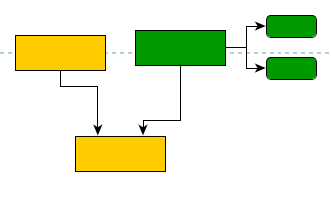
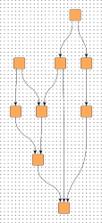
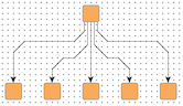
Edge group configurations and resulting bus-style edge routings presents some edge routing results (in the figures to the left) and describes their actual source and target group setup. Note that the figures to the right depict the edge routing that results when both the edges are reversed and the source and target groups are exchanged.
| Figure | Description | Figure |
|---|---|---|
|
Edges starting at A nodes are grouped at their source side using a common A ID (for example). Likewise, edges starting at B nodes are grouped at their source side using a common B ID. Additionally, on their target side, the edges are grouped such that all A edges share a common ID, and all B edges share a common ID. |
|
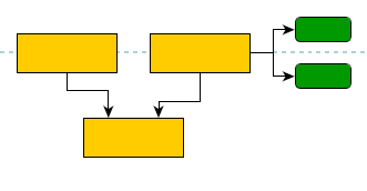
|
Edges starting at the upper nodes are grouped at their target side using a common A ID (for example). Likewise, edges starting at the middle nodes are grouped at their target side using a common B ID. |
|
|
All edges are grouped at their target side using a common ID. |
|
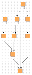
|
All edges are grouped at their source side using a common ID. Additionally, at their target side the edges are also grouped such that they share a common ID. |
|
|
Edges are grouped at their source side using a common ID. |
|


Grid Components
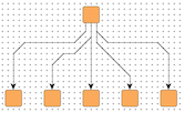
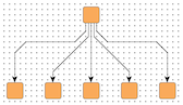
A grid component consists of a root node and bus nodes that are directly connected to the root node by bus edges. The bus nodes are arranged in a grid-like substructure, and the bus edges are routed on a common bus, as shown in figure Hierarchical layout containing a grid component.
All bus edges of a component must have the same edge direction (note that the specified edgeDirectedness is considered). Grid components with outgoing bus edges are placed below the root node, while components with incoming bus edges are placed above the root node (assuming a top-to-bottom layout orientation).

Grid components are arranged in a way that produces more compact layouts. Bus edges are routed using a shared bus segment that connects to the shared root node. The bus nodes are arranged in layers above or below the root node such that the whole substructure occupies a compact area. By default, each layer of the component contains an equal number of bus nodes, bus nodes of adjacent layers are center-aligned, and the bus segment is routed in the middle of the nodes.
|
Tip
|
Defining grid components can make layouts much more compact in scenarios where nodes have many adjacent edges, especially if the successor/predecessor nodes are leaf nodes without further edges. |
To specify a grid component structure, you must map edges to a GridComponentDescriptor instance. Edges with the same descriptor instance and the same direction with respect to a common root node are grouped and form the bus. The mapping can be conveniently defined by using the layout data property gridComponents.
|
Note
|
Some restrictions apply when dealing with grid components. These restrictions are documented here: gridComponents. |
The GridComponentDescriptor allows you to configure the number of nodes that should be placed before and after the common bus segment. See the properties maximumNodesBeforeBus and maximumNodesAfterBus. The terms before and after refer to the ordering in the node sequence (see Terminology). By default, the bus segment is placed in the middle of the bus node sequence. For example, if a layer contains six nodes of the same bus structure, then the bus segment is inserted between the third and the fourth bus node; this example can also be seen in the layout example Hierarchical layout containing a grid component.
If a more specific assignment of nodes to the sides of the bus segment is desired, then you can use nodesBeforeBus. This property allows you to individually state whether a node should be placed before or after the bus. Another more involved configuration option is provided by gridComponentRootOffsets. This feature enables you to specify individual offsets that define the layer in which a bus node is placed with respect to the root node. Thus, an individual bus node layer assignment can be realized. By default, each layer of a grid component contains an equal number of bus nodes (except for the last one if a different number of nodes remain).
Grid Spacing
HierarchicalLayout provides support for placing nodes on grid coordinates. Grid placement is enabled by the following property, which also determines the spacing between grid coordinates:
- gridSpacing
-
Setting a value greater than 0.0 enables grid placement and determines the distance between grid coordinates. The value is used both vertically and horizontally.
The graph’s edges will also be routed on the grid, meaning their bends are placed on grid coordinates, if possible. Placing bends on the grid isn’t always possible depending on other configurations, for example:
-
the configured edge routing style
-
the port coordinates of an edge end when there are strong port constraints set
-
the port assignment policy at a node, which may place edge ends on non-grid coordinates (e.g., DEFAULT, ON_SUBGRID)
The following figures show the results of grid placement with the different edge routing styles supported by HierarchicalLayout. Observe how the center of each node is placed on grid coordinates and edge paths run on grid lines where possible. All figures use a grid spacing value of 10.0 [pixels].
Different grid spacing values can be used to achieve an effect on a graph similar to a scaling transformation:
10.0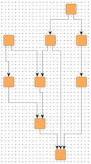
30.0By default, nodes will be placed on the grid with their center. However, you can define an alternative reference point for each node to be used instead. For example, you might want the upper-left corner of a node to be on grid coordinates.
The following property of HierarchicalLayoutNodeDescriptor lets you set the reference point for a node:
- gridReference
-
Determines a node’s reference point, which will be placed on grid coordinates. By default, a node’s center is used as its reference point.
Note that non-empty group nodes will always be placed so that their borders are on grid lines. They are not affected by reference point configuration.
|
Tip
|
When using the Layer Alignment property of the HierarchicalLayoutNodeDescriptor class to top-align (bottom-align) all nodes of a layer, also adjust the reference points of the nodes to their top (bottom) for best results with grid placement. |
To handle the edges of a graph, HierarchicalLayout supports different port assignment policies with grid placement. The policies determine how the edges on each side of a node will be distributed along the respective side.
The portAssignment property in class NodeLayoutDescriptor sets the port assignment policy for a given node. The following policy constants are available:
- DEFAULT
-
Distributes the edges on each node side evenly without considering the grid. This is the default setting that is also used when no grid is specified.
- ON_GRID
-
Distributes the edges on each node side on grid lines. If there are fewer grid lines than there are edges at a side, multiple edges may connect at the same location. When the node is placed on the grid with a reference point on its border, it is possible that there is no grid line available at the node’s side. In that case, all edges at that node side will be centered at the side.
- ON_SUBGRID
-
Distributes the edges on each node side on grid lines. If there are fewer grid lines than there are edges at a side, the grid will be subdivided until there is at least one grid line per edge available.
The following figures show the different port assignment policies with the same graph:
|
Note
|
The grid placement support of HierarchicalLayout does not work well with exact layer coordinate hints or exact sequence coordinate hints. |
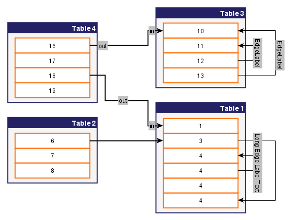
Tables and Swimlanes
HierarchicalLayout supports table layouts, where nodes are arranged within a two-dimensional table of rows and columns. Nodes are placed in predefined cells of the grid structure, and group nodes can span multiple cells to encompass all their child nodes.
Table Layout shows a table layout calculated by HierarchicalLayout, with the layout direction from left to right. The swimlanes are visually represented by a group node that uses the TableNodeStyle node style.
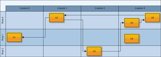
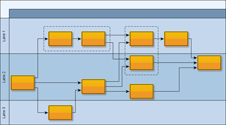
A one-dimensional table, where rows can be seen as horizontal lanes containing nodes (in a left-to-right layout), is also known as a swimlane layout. Swimlane Layout shows an example diagram with nodes organized in lanes.
Setup
The basic setup for calculating a table layout of a graph is described in Tables and Swimlanes. For more complex use-cases that the basic approach does not cover, tables can also be manually specified using the property layoutGridData. More information about this alternative setup can be found in section Customizing Table Layout.
You can see a setup for a table layout with the HierarchicalLayout in the Table Editor Demo.
Tabular Groups
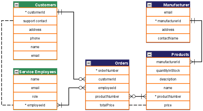
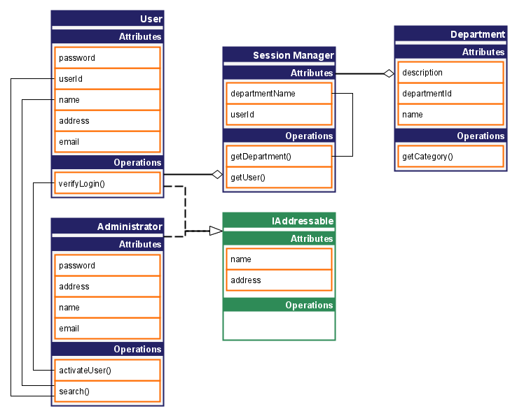
For horizontal layout orientations, a group node can be drawn as a single-column table, with the child nodes acting as table entries. More specifically, the child nodes are placed closely together within the same layer, with a spacing determined by tabularGroupChildDistance. Edges typically connect to these child nodes. A tabular group can also contain nested groups, which will also behave as tabular groups.
Common uses for these structures include visualizing database schemas or UML class diagrams, as shown in the examples below.
As shown in the following snippet, you can mark a group as a tabular group using the property tabularGroups.
// Mark a group node as tabular group
hierarchicalLayoutData.tabularGroups = [groupNode]Note that the overall layout orientation determines the table’s orientation. A horizontal LayoutOrientation (e.g., left-to-right) results in single-column tables, while a vertical orientation results in single-row tables. In either case, the children of a tabular group node are always placed on the same layer.
Ordering of Children inside a Tabular Group
By default, the algorithm orders the children within a tabular group to minimize the number of implied edge crossings.
To specify a particular order, you can use:
-
The property tabularGroupChildComparators property to define custom Comparer functions.
// Use a comparator to arrange the children alphabetically by their label
// Note that you can specify different orders for different tabular groups, if desired
hierarchicalLayoutData.tabularGroupChildComparators.constant = (
  child1: INode,
  child2: INode
) =>
child1.labels.first()!.text.localeCompare(child2.labels.first()!.text)Note that when you specify a custom Comparer for a tabular group, it only applies to the group’s direct children. To apply a custom Comparer to all descendants, including the children of nested groups, you must also attach the Comparer to those nested group nodes. If all groups should use the same ordering, you can simplify the process by using a constant mapping.
Further Notes on Tabular Groups
There are some setups for which a tabular group may not be tight (i.e., maximally compact):
-
If edges connect directly to a tabular group (instead of its content), the group might not become maximally compact.
-
The same is true if there are children with self-loops. Self-loops are always drawn within the tabular group.
-
Also, labels of edges connecting two children of the same tabular group might intersect with other edge segments.
Besides, the groups might not be tight if there are user-specified constraints such as node halos, node labels that are larger than the associated child node, and port constraints connecting to a side orthogonal to the layout orientation.
The tabular group feature of the HierarchicalLayout is demonstrated in the demo application Tabular Groups Demo.
Critical Paths
HierarchicalLayout provides functionality to align nodes that are part of critical paths. This feature emphasizes important edge paths in a diagram.


A critical path in a graph is uniquely defined by its edges. Using the criticalEdgePriorities property, each edge of a critical path is assigned a positive, non-zero value. This value indicates that an edge is part of a critical path. It also defines the priority of the edge and, by extension, the priority of the critical path itself. If edges from different critical paths connect to a common node, the edge with the highest priority determines which nodes are aligned.
|
Tip
|
To further emphasize the importance of an edge, you can increase its crossing cost, which reduces the likelihood of it crossing other edges. Edges of a critical path do not automatically have higher crossing costs. See Edge Crossing Costs for more information about the crossing cost feature. |
The critical paths feature of HierarchicalLayout is demonstrated in the demo application Critical Paths Demo.
Edge Crossing Costs
Edge crossings involving a specific edge can have a custom cost. This cost is considered by the crossing minimization phase of HierarchicalLayout. During this phase, the considered cost for two crossing edges is the product of their individual crossing costs.
Specifying individual costs influences the sequencing of the nodes and allows you to treat some edges with higher priority than others. This is because higher crossing costs mean that it is less likely that an edge will cross with others. However, the crossing minimization is a heuristic algorithm, and it can never be guaranteed that a certain edge will not be crossed, no matter how high the costs are.
Crossing costs are defined using the edgeCrossingCosts property.
Crossing costs with group borders
Crossing costs can also be defined for edges that may cross group node borders. This applies only to vertical group node borders if the layout orientation is vertical and only to horizontal group node borders if the layout orientation is horizontal. In this way, you can specify how undesirable it is for an edge to cross through a group node where it does not start or end. By default, crossing a group node border is more expensive than crossing another edge. You can customize the costs by means of property groupBorderCrossingCosts.
Node Margins
By default, HierarchicalLayout supports node margins as soon as they are declared.
During layout calculation, it considers any specified additional space around nodes and keeps these areas clear of other graph elements. The labels of a node and its adjacent edge segments are not affected and can still be placed inside or cross the node’s margin.
Node margins are specified using the property nodeMargins.