Polyline Edge Routing
Polyline edge routing calculates polyline edge paths for a diagram’s edges. The positions of the nodes in the diagram are not altered by this algorithm.
Edges can be routed orthogonally, i.e., each edge path consists of horizontal and vertical segments, octilinear, or curved. Octilinear means that the slope of each segment of an edge path is a multiple of 45 degree. Curved edges consist of cubic bezier splines.

Relevant Classes
Relevant classes for this algorithm lists the relevant classes for the polyline edge routing algorithm.
| Class Name | Description |
|---|---|
Class EdgeRouter is a layout algorithm for routing edges in a diagram. The positions of the nodes in a diagram are not altered by this algorithm. The algorithm supports routing of all edges at once as well as incremental scenarios where subsequently added edges should be drawn to fit the existing diagram. It can be used to route edges in both flat and grouped graphs.
Basic Options
EdgeRouter provides a set of options that affect the routing behavior. This section highlights some of them.
The scope property determines the (sub-)set of edges that the router should process. When only a subset should be routed, the subset can be specified by means of layout data. Or you can specify a subset of nodes whose connected edges should be routes with layout data.
Note that for edges affected by the scope option, it is possible to specify an individual routing policy, and, depending on it, the edge path may not be changed if it is already deemed to be good.
- ROUTE_ALL_EDGES
- Routes all edges in the graph.
- ROUTE_AFFECTED_EDGES
- Routes only the selected subset of edges in the graph.
- ROUTE_EDGES_AT_AFFECTED_NODES
- Routes only edges which are incident to selected nodes.
- Minimal Node to Edge Distance
- minimumNodeToEdgeDistance
- Determines the distance between edge segments and node sides.
- Grid
- grid
- Specifies the grid on which horizontal and vertical segments of either orthogonal, octilinear, or curved edge paths are placed.
Further routing options can be specified by means of the layout descriptor class for edges. One instance of this class is held by EdgeRouter to store and retrieve default values for routing options, like, e.g., the routing style and the preferred minimum distances between graph elements.
EdgeRouter provides access to the default EdgeLayoutDescriptor instance:
- defaultEdgeLayoutDescriptor
- Edge-related layout options
In addition to the instance held directly by EdgeRouter, layout descriptors can also be associated with single edges in order to specify individual settings for them. Setting individual descriptors for edges is done through layout data.
Routing Style
- routingStyle
- Determines whether the edge routing algorithm creates an orthogonal, octilinear, or curved edge path.
Routing Policy
The policy is an important setting because it determines whether a new edge path is actually calculated. If a policy other than ALWAYS is specified, the existing edge path may be kept in case that it already fulfills certain criteria, e.g., no overlaps with other elements, correct routing style and more.
This provides an intelligent, automatic selection of edges that need to be routed and can be applied to a wide range of interactive scenarios, for example, automatic routing of necessary edges after user interactions like node dragging, group node collapsing/expanding and many more. The consideration of the existing path makes this feature highly suitable for incremental layout scenarios where the sketch provided by the user is relevant.
Importantly, the scope (see description above) still determines whether an edge is even processed by the routing algorithm. Edges that are not affected by the scope are never amended. The policy described here is only relevant for those that are affected.
- routingPolicy
- Indicates if the edge is routed unconditionally or if the existing path is considered to decide
whether routing is necessary.
- ALWAYS: the algorithm always calculates a new path.
- PATH_AS_NEEDED: the algorithm checks the given sketch and calculates a whole new path if a criterion is violated.
- SEGMENTS_AS_NEEDED: the algorithm checks the given sketch and tries to only locally change the path (i.e. some segments) if a criterion is violated. The penalty setting sketchViolationPenalty further determines the importance of the sketch.
Octilinear Routing Style Settings
- preferredOctilinearSegmentLength
- maximumOctilinearSegmentRatio
- Provides additional options for octilinear edge routing which determine the preferred length for the octilinear segment and the ratio between the octilinear segment and the horizontal/vertical segments.
Minimum Edge to Edge Distance
- minimumEdgeToEdgeDistance
- Determines the preferred minimum distance between any two edge segments.
Minimum Length of First and Last Segment
- minimumFirstSegmentLength
- minimumLastSegmentLength
- Determine the preferred minimum length of the first (at the source) and last (at the target) edge segment.
Minimum Distance to Node Corners
- minimumNodeCornerDistance
- Determines the preferred minimum distance between an incident edge and the corners of its node at the side where the edge connects.
Penalty Settings
- penaltySettings
- Configures different penalty settings that are queried during edge routing. Penalties define the costs for various situations, like, e.g., two edge paths crossing, or an edge path crossing a node, etc. Higher penalty for a specific situation means that the edge routing algorithm tries to avoid it and instead looks for other edge paths.
Monotonic Path Restrictions
EdgeRouter supports edge routing such that the generated paths obey so-called monotonic path restrictions. This means that (ideally) each vertical and/or each horizontal segment of an edge path is directed the same way, namely from source node to target node. Thus, when following the edge path, there is never a “turning back” towards the source node, but instead a steady movement towards the target node.
Monotonic edge paths are useful, for example, when routing edges in UML class diagrams/inheritance diagrams or in a tree-like organization chart or to achieve edge routes that are more similar to routes produced by a hierarchical layout, see Edge routes similar to the Hierarchical Layout.
The following property from class EdgeLayoutDescriptor configures monotonic path generation:
- monotonicPathRestriction
- Specifies the kind of monotonic path restrictions for edges.
The following restrictions are available:
- In vertical direction. If possible, each vertical edge segment is directed from source node to target node.
- In horizontal direction. If possible, each horizontal edge segment is directed from source node to target node.
- Combining the former means restricting both directions.
- Clearing monotonic path restrictions can be done by specifying NONE.
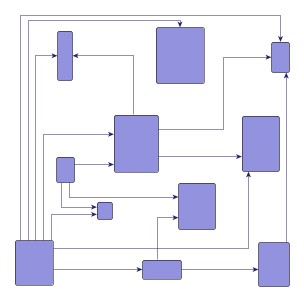
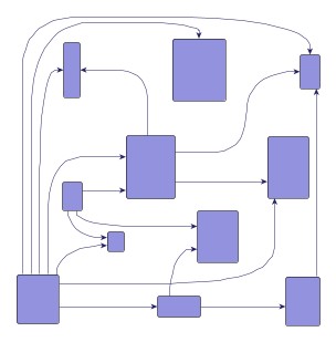
Edge routing with monotonic path restrictions illustrates the results of specifying monotonic edge path restrictions. All figures have specified restrictions in vertical direction, i.e., each vertical edge segment shall be directed from source node to target node.
Edge routes similar to the Hierarchical Layout
The monotonic path restrictions are helpful when one wants to achieve edge routes that have a style similar to the routes produced by HierarchicLayout or generally any layout algorithm that routes edges by obeying a strict flow in a certain direction (depending on the layout orientation). This use-case may arise when single edges in an existing hierarchical layout should be re-routed or inserted without changing the rest of the layout.
Importantly, it is never possible that EdgeRouter produces exactly the same routing style as HierarchicLayout, but using the following settings the style can become more similar:
- Use a monotonic path restriction in vertical direction if the hierarchic layout has a top-to-bottom orientation or a restriction in horizontal direction if the hierarchic layout has a left-to-right orientation.
- Specify PortConstraints on the edges. Use a south-constraint at the source side and a north-constraint at the target side to force the routing algorithm to connect to the ports at the sides that the hierarchical algorithm does with default settings (top-to-bottom layout).
- If the hierarchical layout contains polyline or octilinear edge routes, then set the routingStyle property to octilinear. It can also help to experiment with the setting preferredPolylineSegmentLength. In case the hierarchical layout contains curved edges, set property routingStyle to curved. Note, however, that using orthogonal or curved routes for both layout algorithms will likely make the routes more similar.
Labeling
The polyline edge routing algorithm can be set up to take both node labels and edge labels into account during routing. It considers the size of node labels and labels of fixed edges, i.e., edges that are not to be routed. If space permits, the algorithm will generate edge paths that do not cross through these labels in the resulting diagram.
- Consider Node Labels
- considerNodeLabels
- Specifies whether or not this edge router considers node labels as obstacles for edge paths it calculates.
- Consider Edge Labels
- considerEdgeLabels
- Specifies whether or not labels of edges that are not to be routed by the edge router are considered as obstacles for the edge paths it calculates.
- integratedEdgeLabeling
- Specifies whether or not the edge routing algorithm will place edge labels.
Grouped Graphs
EdgeRouter supports routing in grouped graphs without further setup. It recognizes group nodes and folder nodes and finds edge paths to nodes grouped within group nodes.
Incremental Layout
EdgeRouter supports incremental routing through the Scope feature. See the above description.
Furthermore, the routing policy setting is relevant for incremental routing. If it is not clear which edges the algorithm should route, an automatic selection can be realized with a combination of scope ROUTE_ALL_EDGES and routing policies PATH_AS_NEEDED or SEGMENTS_AS_NEEDED. When only locally routing segments as needed, the following advanced penalty setting is available to specify the importance of the provided sketch: sketchViolationPenalty.
Port Constraints
EdgeRouter supports both weak port constraints as well as strong port constraints that are specified for the edges of a graph (more precisely, the edge ends). The setup of port constraints is presented in Port Constraints.
Using weak port constraints for the ends of an edge, it is possible to specify at which side of the source node or target node, respectively, an edge path must connect.
Using strong port constraints, it is possible to specify the side of the node at which an edge must connect, and additionally also the exact position of the port.
Both weak port constraints and strong port constraints can be mixed easily in the drawing.
You can specify the port constraints for the source node as well as for the target node for each edge by means of layout data.
Port Candidates
In addition to the support provided for port constraints, polyline edge routing also supports the concept of port candidates. Both aspects, i.e., matching port candidates as well as modeling enhanced port constraints are supported.
For the matching of port candidates, you can specify the set of allowed anchor locations for edge ends at the nodes of a graph by means of layout data. The same applies to the subset of desired anchor locations where the source ports and target ports of edges like to connect.
See Port Candidates for Nodes for a detailed description of the port candidates concept.
Edge Grouping
Polyline edge routing supports the notion of grouping together multiple edge ends to be anchored at the same location. This can be specified for both source ends and target ends. The general setup for edge groups is described in Layout with Edge Grouping.
Bus-style routing
In addition to edge and port grouping, EdgeRouter also supports orthogonal bus-style routing. A bus is a segment shared by multiple edges to which shorter segments that connect to the actual nodes are attached to. The bus consists of possibly multiple backbone segments, which are always routed orthogonal. The shorter segments connecting to the actual nodes can, like any other edge, also be routed with the polyline style. Bus-style routing is a suitable solution for parts of a diagram where each node is connected to each other node (complete sub-graphs).
Usage
To define a bus use the layout data property buses. On the object returned from that property add one or more EdgeRouterBusDescriptor instances to create a new bus. The returned ItemCollectionMapping<TItem,TValue> allows to conveniently define which edges should be part of the created bus. The descriptor instance serves as a way to configure the settings of the bus itself. The multipleBackboneSegments property allows to specify whether a bus may consist of multiple backbone segments (default) or just a single one. The following code example illustrates how to define two different buses.
const graph = this.getMyGraph()
const edgeRouter = new EdgeRouter()
const edgeRouterData = new EdgeRouterData()

// the first bus consists of all edges that are red (assuming the used edge style is PolylineEdgeStyle)
// - for this use case the simple Delegate property is used
const firstBus = new EdgeRouterBusDescriptor({
  automaticEdgeGrouping: false
})
edgeRouterData.buses.add(firstBus).delegate = (edge) => edge.style.stroke === Stroke.RED

// the second bus is defined by a given list of edges filled by some user-defined method
// - we use the appropriate Items property in this case
const secondBus = new EdgeRouterBusDescriptor()
secondBus.automaticEdgeGrouping = true
secondBus.minimumBackboneSegmentLength = 200
const secondBusEdges = this.getSecondBusEdges()
edgeRouterData.buses.add(secondBus).items = secondBusEdges
// Apply the edge routing algorithm
graph.applyLayout(edgeRouter, edgeRouterData)
const graph = this.getMyGraph()
const edgeRouter = new EdgeRouter()
const edgeRouterData = new EdgeRouterData()

// the first bus consists of all edges that are red (assuming the used edge style is PolylineEdgeStyle)
// - for this use case the simple Delegate property is used
const firstBus = new EdgeRouterBusDescriptor({
  automaticEdgeGrouping: false
})
edgeRouterData.buses.add(firstBus).delegate = (edge: IEdge) =>
  (edge.style as PolylineEdgeStyle).stroke === Stroke.RED

// the second bus is defined by a given list of edges filled by some user-defined method
// - we use the appropriate Items property in this case
const secondBus = new EdgeRouterBusDescriptor()
secondBus.automaticEdgeGrouping = true
secondBus.minimumBackboneSegmentLength = 200
const secondBusEdges: ICollection<IEdge> = this.getSecondBusEdges()
edgeRouterData.buses.add(secondBus).items = secondBusEdges
// Apply the edge routing algorithm
graph.applyLayout(edgeRouter, edgeRouterData)
Tables
EdgeRouter supports routing in partition grids without further setup. It recognizes swimlane nodes/partition grids and finds edge paths to nodes within partition cells.
To know about the layout of a partition grid’s rows and columns, it uses the services of class PartitionGrid. You can specify the PartitionGrid by means of layout data.
Node Halos
EdgeRouter by default supports node halos as soon as they are declared. It considers any specified additional padding around nodes and if space permits, the algorithm will generate edge paths that do not cross through these areas in the resulting diagram. Other constraints (e.g. port constraints) that have higher costs associated, can cause edges to cross node halos, however.
Layout Data
When using class EdgeRouter, supplemental layout data for a graph’s elements can be specified either by using class EdgeRouterData or by registering data providers with the graph using given look-up keys. Supplemental layout data lists all properties of EdgeRouterData and the corresponding look-up keys that EdgeRouter tests during the layout process in order to query supplemental data.
Providing supplemental layout data is described in detail in Layout Data.
Supplemental layout data
affectedEdges - For each edge a boolean value indicating whether the edge shall be considered for rerouting or not.Data Provider Key: affectedEdgesDpKeyMaps from edge to boolean
affectedNodes - For each node a boolean value indicating whether the edges connected to this node shall be considered for rerouting or not.Data Provider Key: affectedNodesDpKeyMaps from node to boolean
edgeLayoutDescriptors - For each edge an EdgeLayoutDescriptor object that configures a number of edge-related options.Data Provider Key: EDGE_LAYOUT_DESCRIPTOR_DP_KEYMaps from edge to EdgeLayoutDescriptor
sourcePortConstraints - For each edge a PortConstraint object encoding its source end’s port constraint.Data Provider Key: SOURCE_PORT_CONSTRAINT_DP_KEYMaps from edge to PortConstraint
targetPortConstraints - For each edge a PortConstraint object encoding its target end’s port constraint.Data Provider Key: TARGET_PORT_CONSTRAINT_DP_KEYMaps from edge to PortConstraint
sourceGroupIds - For each edge an arbitrary object indicating the group its source end is affiliated with.Data Provider Key: SOURCE_GROUP_ID_DP_KEYMaps from edge to object
targetGroupIds - For each edge an arbitrary Object indicating the group its target end is affiliated with.Data Provider Key: TARGET_GROUP_ID_DP_KEYMaps from edge to object
sourcePortGroupIds - For each edge an arbitrary Object indicating the port group its source end is affiliated with.Data Provider Key: SOURCE_PORT_GROUP_ID_DP_KEYMaps from edge to Object
targetPortGroupIds - For each edge an arbitrary Object indicating the port group its target end is affiliated with.Data Provider Key: TARGET_PORT_GROUP_ID_DP_KEYMaps from edge to Object
buses - For each edge the bus descriptor instance indicating the bus to which the edge belongs to.Data Provider Key: BUS_DESCRIPTOR_DP_KEYMaps from edge to BusDescriptor
nodePortCandidateSets - For each node a PortCandidateSet object encoding the set of allowed anchor locations for bus connections.Data Provider Key: NODE_PORT_CANDIDATE_SET_DP_KEYMaps from node to PortCandidateSet
sourcePortCandidates - For each edge a ICollection<T> of PortCandidate objects that encode the subset of desired anchor locations where the source port likes to connect to.Data Provider Key: SOURCE_PORT_CANDIDATE_COLLECTION_DP_KEYMaps from edge to Collection
targetPortCandidates - For each edge a ICollection<T> of PortCandidate objects that encode the subset of desired anchor locations where the target port likes to connect to.Data Provider Key: TARGET_PORT_CANDIDATE_COLLECTION_DP_KEYMaps from edge to Collection
partitionGridData - A PartitionGrid object that specifies the actual partition grid, including number of rows and columns, their respective heights and widths, and their insets.Data Provider Key: PARTITION_GRID_DP_KEYMaps from graph to PartitionGrid
nodeHalos - A NodeHalo object that specifies the halo sizes at each side of a node.Data Provider Key: NODE_HALO_DP_KEYMaps from node to NodeHalo
abortHandler - An AbortHandler instance that will be queried by the layout algorithm to determine whether layout calculation shall be terminated.Data Provider Key: ABORT_HANDLER_DP_KEYMaps from graph to AbortHandler
ignoredLabels - A collection of labels of nodes or fixed edges that are ignored by the router.Data Provider Key: IGNORED_LABELS_DP_KEYMaps from label to boolean
labelCrossingPenaltyFactors - For each label a penalty factor that is multiplied with the basic penalty for an edge crossing the label.Data Provider Key: LABEL_CROSSING_PENALTY_FACTOR_DP_KEYMaps from label to double