Bus-style Edge Routing
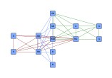
Orthogonal bus-style edge routing combines the (likely confusing) mass of edges in parts of a diagram where each node is connected to each other node in a concise, tree-like structure that consists of vertical and horizontal line segments. The positions of the nodes in a diagram are not altered by this algorithm.
The algorithm aims to find routes where all edge paths share as much way as possible. It yields long line segments where ideally all but the first and last segments of all edge paths are drawn on top of each other, with short connections branching off to the nodes. The short connections bundle the respective first or last segments of a node’s incident edges.
Carefully observe that the resulting representation, with many edge segments drawn on top of each other, leaves little room for a sensible interpretation of edge direction.
Terminology
This routing style works on the set of edges of a complete (sub)graph, (a part of) a diagram where each node is connected to a each other node. Mathematically, this set of edges is equivalent to a hyperedge, an edge that not only connects two nodes, but a set of nodes with each other.
The orthogonal edge paths that are calculated for the set of edges form a representation that, in its entirety, is called bus-style representation or often also simply bus. This bus consists of bus connections, which simply mean the (ideally) short line segments directly starting at the nodes, and the backbone segments.
Backbone segments are "at the heart" of the representation and refer to the vertical and horizontal line segments where the line segments from the nodes (the bus connections) end.
The orthogonal bus-style edge routing algorithm uses a two-phase process, basically:
- Find a set of good initial backbone segments. This phase is referred to as the backbone selection phase.
- Connect initial backbone segments with each other and also each node to each of the initial backbone segments by using orthogonal edge paths. Reduce the set of resulting structures to the most optimal structure where backbone segments are long and bus connections from the nodes are short. This phase is referred to as the routing and recombination phase.
Relevant Classes
The relevant classes for the orthogonal bus-style edge routing algorithm are
- BusRouter
- Main algorithm. See the description below.
- BusDescriptor
- Provides bus-related configurations for an edge. Determines the bus ID, most notably. See Bus-related Options.
- BusRepresentations
- Facilitates generation of the set of edges of a complete subgraph from a conceptually equivalent reduced structure, the hub structure. Also supports conversion of bus-style representations to hub structures.
Class BusRouter is a layout algorithm for routing the set of edges of complete subgraphs. The positions of the nodes in a diagram are not altered by this algorithm.
The edge paths that are generated by this algorithm form a so-called bus-style representation that consists of vertical and horizontal line segments only, where many edge paths are drawn on top of each other. This bus-style representation resembles a tree-like structure that connects the nodes.
Setup
To calculate actual bus-style representations, BusRouter needs a mapping to determine which edges belong to a common bus. The mapping that assigns a bus ID to each edge can be specified using the BusDescriptor class by means of layout data. Note that for an edge without bus ID, a bus consisting only of the single edge is created.
const graph = getMyGraph()

// Create bus ID objects.
const myBusID = 'This is the first bus.'
const myOtherBusID = 'A second bus.'

// Create a mapper.
const em = new Mapper()

// Establish a mapping from edges to bus IDs.
graph.edges.forEach((e) => {
  if (doesEdgeBelongToFirstBus(e)) {
    em.set(e, new BusRouterBusDescriptor(myBusID))
  } else if (doesEdgeBelongToSecondBus(e)) {
    em.set(e, new BusRouterBusDescriptor(myOtherBusID))
  }
  // If there is no BusDescriptor for an edge in the data provider, the edge
  // will be routed as a "bus of its own" consisting only of the single edge.
})

// Add the mapper to the mapper registry of the graph.
graph.mapperRegistry.addMapper(IEdge.$class, BusRouterBusDescriptor.$class, BusRouter.EDGE_DESCRIPTOR_DP_KEY, em)

// Invoke the layout.
graph.applyLayout(new BusRouter())
const graph = getMyGraph()

// Create bus ID objects.
const myBusID = 'This is the first bus.'
const myOtherBusID = 'A second bus.'

// Create a mapper.
const em = new Mapper<IEdge, BusRouterBusDescriptor>()

// Establish a mapping from edges to bus IDs.
graph.edges.forEach((e) => {
  if (doesEdgeBelongToFirstBus(e)) {
    em.set(e, new BusRouterBusDescriptor(myBusID))
  } else if (doesEdgeBelongToSecondBus(e)) {
    em.set(e, new BusRouterBusDescriptor(myOtherBusID))
  }
  // If there is no BusDescriptor for an edge in the data provider, the edge
  // will be routed as a "bus of its own" consisting only of the single edge.
})

// Add the mapper to the mapper registry of the graph.
graph.mapperRegistry.addMapper(IEdge.$class, BusRouterBusDescriptor.$class, BusRouter.EDGE_DESCRIPTOR_DP_KEY, em)

// Invoke the layout.
graph.applyLayout(new BusRouter())
Basic Options
BusRouter provides a set of options that affect the routing behavior. This section highlights some of the configuration options available.
The scope property determines the set of edges that the router should process. When only a subset should be routed, the subset can be specified by means of layout data.
- ROUTE_ALL_EDGES
- Routes all edges in the graph.
- ROUTE_AFFECTED_EDGES
- Routes only the specified subset of edges in the graph.
The following properties affect the backbone selection phase of the algorithm, where good initial backbone segments are calculated.
- Minimum Backbone Segment Length
- minimumBackboneSegmentLength
- Sets the minimum length of a backbone segment. This value is used to select initial backbone segments. Note that the final lengths of backbone segment may not comply with this setting.
- Preferred Backbone Segment Count
- preferredBackboneSegmentCount
- Sets the preferred number of backbone segments with the same orientation. This value is used to select initial backbone segments. Note that the final number of vertical (horizontal) backbone segment may not comply with this setting.
During the routing and recombination phase, these settings are used:
- Minimum Bus Connections Count
- minimumBusConnectionsCount
- Determines the minimum number of bus connections a backbone segment must have.
- Crossing Cost
- crossingCost
- Determines a "penalty" for edge crossings. Good values for a crossing penalty lie in the range from 1.0 to 3.0. By default this value is set to 1.0.
Distances and grid routing options have effect across all phases.
- Minimum Edge Distance
- minimumDistanceToEdge
- Determines the distance between any two edge segments.
- Minimum Distance to Node
- minimumDistanceToNode
- Determines the distance between edge segments and node sides.
- Route on Grid
- gridRouting
- If set, then all edge paths will be routed on grid lines of a predefined grid.
The bus ID, respectively the group ID, defines a strong relationship amongst edges. Edge ends at a common node from edges of the same bus connect to the node using a common location (thus forming a bus connection). Similarly, a common location is also used to connect all edge ends to the node whose edges have the same bus ID and where the edge ends have the same group ID associated. The respective common location for such a set of edge ends can be influenced using:
Bus-related Options
Class BusDescriptor configures bus-related options for edges. The following options can be set:
- the bus an edge belongs to
- whether an edge is fixed, i.e., whether it is part of the bus-style representation that shall remain unaltered when buses are rearranged
- an optional group ID for an edge’s source end and target end, respectively
Creating the mapping for buses shows how a BusDescriptor for a bus is created and associated with edges of a graph.
The descriptor class provides a number of options for bus configuration which are described in detail below.
Bus ID
- busId
- Determines the bus ID of an edge.
Fixed Edge
Support for incremental scenarios is provided by the following property. The paths of non-fixed edges are calculated anew when rearranging an existing bus-style representation.
- fixed
- Determines whether an edge is fixed or not. The paths of non-fixed edges will be routed anew when rearranging an existing bus-style representation.
Edge Grouping
The following properties allow to set optional group IDs for edge ends. These serve to partition the set of edge ends connected to a node and allow to create separate bus connections at a node.
Note that although the direction of the edges is irrelevant for bus-style edge routing in general, it becomes relevant in conjunction with setting group IDs. To allow different group IDs for the ends of an edge, the terms "source" end and "target" end of the underlying technical representation of an edge come into play.
- Group IDs
- sourceGroupId
- Determines the group ID of an edge’s source end. Group IDs allow to create separate bus connections at a node.
- targetGroupId
- Determines the group ID of an edge’s target end. Group IDs allow to create separate bus connections at a node.
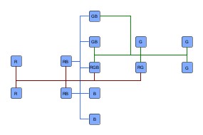
Separate bus connections at nodes are illustrated in Edge grouping by IDs.
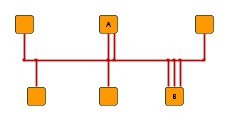
The group IDs for the edge ends connecting to node B in the above figure could have been set up using the following code:
const graph = getMyGraph()
const nodeB = getMyNode()

const numberOfGroups = 3

// Setup of group IDs for edge ends at node 'B' (nodeB).
graph.inEdgesAt(nodeB).forEach((e, i) => {
  const /** BusRouterBusDescriptor */ bd = getMyBusDescriptorForEdge(e)
  // Set the group ID for the edge end connecting to nodeB.
  bd.targetGroupId = i++ % numberOfGroups
})
Routing Policy
The policy is important because it determines whether a new edge path is actually calculated. If policy PATH_AS_NEEDED is specified, the existing edge path may be kept in case that it already fulfills certain criteria, e.g., no overlaps with other elements, correct routing style and more.
This provides an intelligent, automatic selection of edges that need to be routed and can be applied to a wide range of interactive scenarios, for example, automatic routing of necessary edges after user interactions like node dragging, group node collapsing/expanding and many more. The consideration of the existing path makes this feature highly suitable for incremental layout scenarios where the sketch provided by the user is relevant. Importantly, the policy described here is only relevant for those that are not fixed. Fixed edges are never amended.
- routingPolicy
- Indicates if the edge is routed unconditionally or if the existing path is considered to decide
whether routing is necessary.
- ALWAYS: the algorithm always calculates a new path (default).
- PATH_AS_NEEDED: the algorithm checks the given sketch and calculates a whole new path if a criterion is violated.
Hub Structure
Class BusRepresentations is a utility class that provides convenience conversion support related to bus representations.
BusRepresentations can be used to easily create the set of edges of a complete subgraph from a hub structure, a conceptually equivalent structure that uses a reduced number of edges which connect the (regular) nodes to a number of artificially introduced, so-called hub nodes. The hub nodes serve as a means to facilitate convenient definition of this structure.
A hub structure is a tree-like representation of a hyperedge, with the nodes of the complete subgraph being the leaves, and both root node and (an arbitrary number of) inner nodes denoted by the term hub nodes.
Hub nodes can be specified by means of a data provider holding boolean values, which is used with the following static conversion methods:
- replaceHubsBySubgraph(graph: LayoutGraph, hubMarker: IDataProvider, descriptorAcceptor: IDataAcceptor): EdgeList
- replaceHubsBySubgraph(graph: LayoutGraph, hubEdgesLists: EdgeList[], hubMarker: IDataProvider, fixedMarker: IDataProvider, descriptorAcceptor: IDataAcceptor): EdgeList
- Converts a hub structure to the set of edges of a complete subgraphs by creating new edges between regular nodes and removing the hub nodes.
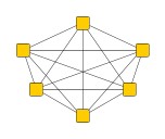
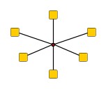
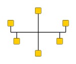
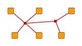
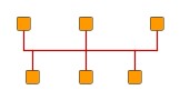
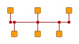
Hub structures are tree-like and can be specified as needed, i.e., there is no "canonical" way that a hub structure needs to look like to achieve a specific complete subgraph. For example, a minimal hub structure would consist of a single hub node where all regular nodes connect to. The first two structures in Hub structures are conceptually equivalent hub structures that represent the same hyperedge. The last figure shows the routing result for both.
Converting the bus-style representation back to a hub structure is supported by the following method:
- replaceSubgraphByHubs(graph: LayoutGraph, edgeCursor: IEdgeCursor, descriptorProvider: IDataProvider, busIDAcceptor: IDataAcceptor): void
- Converts the bus-style representation of the edges of a complete subgraph to a hub structure. Replaces bends in the bus-style representation and connection points of bus connections at backbone segments with hub nodes and uses only edges between hub nodes and hub nodes and regular nodes. The edge paths must form an orthogonal, cycle-free bus. Note that the hub structure is generated from the actual edge paths of the bus-style representation.
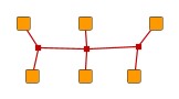
Hub structure after layout and conversion shows the resulting hub structure after converting the bus-style representation as routed in Hub structures. Observe that there are five hub nodes that reflect the actual routes of the edge paths. Overall, this graph has 6 regular nodes, 5 hub nodes, and 10 edges (4 edges between hub nodes).
Incremental Layout
Incremental routing means generation of a bus-style representation using an already existing bus-style representation as sketch. It can be used when
- new edges are added to a bus, or when
- a node of the bus is moved, and its incident edges need to be routed anew.
Incremental routing of bus-style representations is supported by denoting so-called fixed edges using the fixed property of BusDescriptor When rearranging existing edges or adding new nodes and edges to an existing bus, the paths of non-fixed edges are calculated anew. The structure induced by the fixed edges must be orthogonal and cycle-free.
In the initial phase, appropriate backbone segments are determined from the structure of the fixed edges with respect to the settings minimumBackboneSegmentLength and preferredBackboneSegmentCount. In the second phase, bus connections from nodes of non-fixed edges to the determined backbone segments are calculated as described above.
Polyline Routing
PolylineLayoutStage can add octilinear edge routing to a diagram that results from the orthogonal bus-style edge routing calculation. For this, use class BusRouter as the core layout algorithm of the layout stage.
Port Constraints
Orthogonal bus-style edge routing obeys both types of port constraints, weak and strong. The port constraints can be specified for the source as well as for the target by means of layout data.
If edge ends at a common node from edges of the same bus are associated with inconsistent or even contradicting port constraints, then any of these port constraints can determine the actual location of the common port. The same holds for the common port of edge ends from edges that in addition have the same group ID.
Port Candidates
In addition to the support provided for port constraints, orthogonal bus-style edge routing also supports the concept of port candidates. Both aspects, i.e., matching port candidates as well as modeling enhanced port constraints are supported.
For the matching of port candidates, the set of allowed anchor locations for bus connections at the nodes can be specified by means of layout data. The same also applies to the subset of desired anchor locations where the source ports and target ports of edges like to connect.
The cardinality defined with a PortCandidateSet object is interpreted in terms of different bus IDs (group IDs) instead of number of edges.
See Port Candidates for Nodes for a detailed description of the port candidates concept.
If edge ends at a common node from edges of the same bus are associated with inconsistent or even contradicting port candidates, then any of these port candidates can determine the actual location of the common port. The same holds for the common port of edge ends from edges that in addition have the same group ID.
The following table lists the data provider look-up keys that are recognized by BusRouter in conjunction with port candidates.
| Key | Element Type | Value Type | Description |
|---|---|---|---|
Esthetic Buses
Values of at least 3 (the default) for property minimumBusConnectionsCount result in longer backbone segments and clearly visible bus-like representations. The value should be increased for large graphs.
The value for property minimumBackboneSegmentLength should be at least as large as the typical width (height) of a node in the diagram.
Layout Data
When using class BusRouter, supplemental layout data for a graph’s elements can be specified either by using class BusRouterData or by registering data providers with the graph using given look-up keys. Supplemental layout data lists all properties of BusRouterData and the corresponding look-up keys that BusRouter tests during the layout process in order to query supplemental data.
Providing supplemental layout data is described in detail in Layout Data.
Supplemental layout data
edgeDescriptors - For each edge a BusDescriptor object that configures a number of bus-related configuration options, most notably, an edge’s bus ID.Data Provider Key: EDGE_DESCRIPTOR_DP_KEYMaps from edge to BusDescriptor
affectedEdges - For each edge a boolean value indicating whether it should be routed or not.Data Provider Key: DEFAULT_AFFECTED_EDGES_DP_KEYMaps from edge to boolean
sourcePortConstraints - For each edge a PortConstraint object encoding its source end’s port constraint.Data Provider Key: SOURCE_PORT_CONSTRAINT_DP_KEYMaps from edge to PortConstraint
targetPortConstraints - For each edge a PortConstraint object encoding its target end’s port constraint.Data Provider Key: TARGET_PORT_CONSTRAINT_DP_KEYMaps from edge to PortConstraint
nodePortCandidateSets - For each node a PortCandidateSet object encoding the set of allowed anchor locations for bus connections. Note that the cardinality defined with a PortCandidateSet object is interpreted in terms of different bus IDs (group IDs) instead of number of edges.Data Provider Key: NODE_PORT_CANDIDATE_SET_DP_KEYMaps from node to PortCandidateSet
sourcePortCandidates - For each edge a ICollection<T> of PortCandidate objects that encode the subset of desired anchor locations where the source port likes to connect to.Data Provider Key: SOURCE_PORT_CANDIDATE_COLLECTION_DP_KEYMaps from edge to Collection
targetPortCandidates - For each edge a ICollection<T> of PortCandidate objects that encode the subset of desired anchor locations where the target port likes to connect to.Data Provider Key: TARGET_PORT_CANDIDATE_COLLECTION_DP_KEYMaps from edge to Collection
abortHandler - An AbortHandler instance that will be queried by the layout algorithm to determine whether layout calculation shall be terminated.Data Provider Key: ABORT_HANDLER_DP_KEYMaps from graph to AbortHandler