Item Layout
Each item has a specific method for determining its location on the canvas. Some items use absolute coordinates, while others are described relative to another item.
|
Tip
|
Even though the layout is a property of the item itself (as every property of a model item is), the graph that the item resides in is responsible for managing it. Thus, the layout can only be set via the graph instance. |
|
Tip
|
The location of the graph elements can be specified programmatically by the developer (as shown here), interactively by the user, or automatically by one of yFiles for HTML’s many advanced layout algorithms. |
Nodes
Nodes are the only truly independent type of graph elements. Therefore, they are the only items that always have an absolute and independent layout.
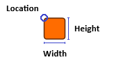
The layout of a node is defined as a rectangle in world coordinates. The rectangle is defined by its top left corner, width, and height. It also defines the logical bounds for that item (with regard to layout calculation, hit testing, hovering, etc.).
|
Note
|
The rectangle object that is returned by the property on the node type is a live view on the layout. This means that the object always holds the current coordinates. |
The layout is defined on the layout property of an INode. The property is read-only. Its value can only be set using methods of IGraph.
The layout can be set initially, either using default values or by providing it as a parameter of the createNode:
// set the default size for nodes to 60, 40
graph.nodeDefaults.size = new Size(60, 40)
// creates a node with a default layout, i.e. 0, 0, 60, 40
const node1 = graph.createNode()

// creates a node with the given layout
const node2 = graph.createNode(new Rect(100, 100, 60, 40))To set the layout of an existing node, use IGraph's method setNodeLayout:
// changes the layout of an existing node
graph.setNodeLayout(node, new Rect(x, y, width, height))The node’s layout can also be set indirectly, for example, by adjusting a group node’s bounds, by user interaction, or by an automatic layout.
Edges
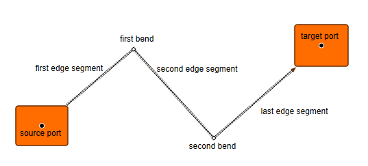
The layout of an edge is defined by a source port, a target port, and the edge path. The source port (IEdge.sourcePort) is the port at which the edge logically starts, and the target port (IEdge.targetPort) is the port at which the edge logically ends. In this sense, the edge is logically directed toward the target port.
|
Note
|
For directed graphs, the edge direction can be emphasized visually by arrows that point to the source or target port. Note that some layout algorithms consider the direction of the edges. |
|
Note
|
The layout, i.e., the exact location, of the ports can be determined for each port as shown in the section about port layout. |
The edge path is defined as an ordered list of bends (IEdge.bends). The order of the bends in the list determines the path: the edge starts at the source port, and the segment between the source port and the first bend in the list is the first edge segment. The next edge segment connects the first bend with the second. Finally, the last bend connects with the target port for the last edge segment.
The ports and the list of bends are managed by IGraph. Edges can be reconnected to other ports via setEdgePorts:
// sets source and target port to new ports
graph.setEdgePorts(edge, port1, port2)

// keeps the source port but sets the target to a new port on a new node
graph.setEdgePorts(edge, edge.sourcePort, node.ports.get(0))Bends can be added (addBend) or relocated (setBendLocation) as well as removed (remove):
// adds a new bend at 20, 50
const bend = graph.addBend(edge, new Point(20, 50))

// moves the bend to 50, 50
graph.setBendLocation(bend, new Point(50, 50))

// removes the bend from its edge
graph.remove(bend)Labels
As labels in most cases serve as a description or nameplate for items, they are modeled as “owned” by other items (so-called ILabelOwners, like nodes, edges, or ports). Generally, they should be positioned near their owner and move accordingly when their respective owner is moved. Because of this, the layout of labels is defined relative to their owner’s layout.
For this, the layout of a label is defined by a label model and the corresponding label model parameter. The label model calculates the geometry of the label based on the label model parameter.
|
Note
|
The label implementation only holds the label model parameter because the parameter knows its own label model. |
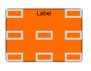
For example, the InteriorNodeLabelModel is a label model that places a label inside its node, along the node’s borders. The border is determined by the label model parameter. The label model provides the parameters TOP, RIGHT, BOTTOM, etc.
The label model parameter of a label is available via its layoutParameter property, which is read-only. Therefore, the label model parameter has to be set using methods of the IGraph instance the label is part of. When creating a new label, the desired label model parameter may be passed to the method addLabel. The label model parameter of an existing label can be set with the method setLabelLayoutParameter:
// Creates a new label with the default label model parameter for node labels
graph.addLabel(node, 'A Label')

// Creates a new label with the given predefined label model parameter
graph.addLabel(node, 'A Label', InteriorNodeLabelModel.CENTER)

// creates a new label with the given calculated label model parameter
graph.addLabel(
  edge,
  'A Label',
  new EdgeSegmentLabelModel(
    10,
    0,
    0,
    false,
    EdgeSides.ABOVE_EDGE
  ).createParameterFromSource(0, 0.5, EdgeSides.ABOVE_EDGE)
)

// sets a new label model parameter. Note that this example model can only
// be used with a label of a node.
graph.setLabelLayoutParameter(label, ExteriorNodeLabelModel.BOTTOM)It is up to the label model implementation how the geometry of the label is calculated and what factors are taken into consideration. The result of this calculation is provided to the visualization as an area to draw the label into; see also the section The Preferred Label Size. The TOP parameter, as shown above, for example, places the label in a way that the top of its bounding box is aligned with the top of the node’s bounding box, and its horizontal center is aligned with the horizontal center of the node.
One common factor for geometry calculation in the label models is the preferred size of a label. There are two ways the preferred size of a label is determined:
-
Directly by setting the property of the label.
-
Indirectly by the visualization logic for the label.
You should rarely need to set the preferred size property directly on the label. This is an uncommon practice. Its main uses are cases in which no other information is available (such as when the actual size of the text on the screen is unknown before the application has finished loading), or when the space for the label is limited beforehand.
// creates a new label with the given preferred size
graph.addLabel({
  owner: node,
  text: 'A Label',
  preferredSize: new Size(100, 15)
})

// creates a new label but lets the label style calculate the preferred size
graph.addLabel(node, 'A Label')

// sets the preferred size of an existing label
graph.setLabelPreferredSize(label, new Size(10, 40))The common case is that the graph sets the preferred size of the label when the property is not set explicitly. In this case, the visualization for the label (its style) determines how big the label visualization would be if all aspects were known (such as font and font size, for example) and the label had theoretically unlimited space in the canvas.
The preferred size is re-calculated each time a label is created without a preferred size provided, a new text is set, or a new style is set. Therefore it is rarely necessary to calculate it explicitly. However, if you have to, you should use the style’s renderer to do it:
// calculates the preferred size for the given label and sets it
const preferredSize = label.style.renderer.getPreferredSize(
  label,
  label.style
)
graph.setLabelPreferredSize(label, preferredSize)|
Important
|
However you specify the preferred size, keep in mind that the label model implementation determines whether to honor this preferred size. The result of the label model’s geometry calculation defines the layout of the label, which is later the area that the visualization is instructed to draw the label into. |
There are various predefined label models available for different scenarios. Typically, a model provides one or more factory methods for creating label model parameters. Some of the models support only a fixed set of parameters. In these cases, the parameters can be accessed using predefined constants (such as in the example above).
- InteriorNodeLabelModel
-
Provides nine specific positions inside the node’s bounds.
- ExteriorNodeLabelModel
-
Provides eight specific positions outside the node’s bounds.
- StretchNodeLabelModel
-
Places the label inside the node’s bounds and makes the label fit either the node’s width or height.
- FreeNodeLabelModel
-
The label can be placed at any position, either a fixed location anywhere in the graph or a location relative to the node’s bounds. Optionally, proper interactive positioning is eased by a sophisticated snapping to special positions.
- GroupNodeLabelModel
-
Places the label inside the tab or tab background area of a GroupNodeStyle instance.
- NinePositionsEdgeLabelModel
-
Provides nine specific label positions near the source, center, and target of the edge.
- SmartEdgeLabelModel
-
The most versatile edge label model. The label can be placed at any location and is anchored relative to the nearest edge segment. Optionally, proper interactive positioning is eased by a sophisticated snapping to special positions.
- EdgeSegmentLabelModel
-
Allows placement of labels directly on the edge path or on one side of the edge at a given distance. By default, a set of position candidates along the edge is presented to the user during interactive movements, but the model itself supports continuous positions. The label’s position is determined by the index of an edge segment and the ratio along this segment.
- EdgePathLabelModel
-
Allows placement of labels directly on the edge path or on one side of the edge at a given distance. By default, a set of position candidates along the edge is presented to the user during interactive movements, but the model itself supports continuous positions. The label’s position is determined by the ratio along the entire edge path.
- FreeEdgeLabelModel
-
The label can be placed at any location and is anchored relative to the edge’s port location. Optionally, proper interactive positioning is eased by a sophisticated snapping to special positions.
- InsideOutsidePortLabelModel
-
Places the label either inside or outside of the owner node of the port, according to the node border which is closest to the port position.
- FreePortLabelModel
-
The label can be placed at any location and is anchored relative to the port’s location. Optionally, proper interactive positioning is eased by a sophisticated snapping to special positions.
The actual label layout is determined by the layoutParameter and is often relative to the label’s owner. The layout property provides a convenient way to get a snapshot of the label’s current layout. Since a label can be rotated, the layout is provided as IOrientedRectangle.
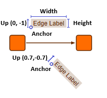
Note that the location of the oriented rectangle is provided by an anchor point, which is the bottom left corner of the rectangle. Its angle is determined by a so-called up vector, as shown in the figure above.
- layout: IOrientedRectangle
-
Returns a snapshot of the current layout of the label.
Ports
Similar to labels, ports are items that cannot exist independently of other elements; specifically, nodes and edges (IPortOwners). Therefore, their layout depends on these owner items and aligns with them in every situation.
The layout of a port is defined by a point (the port’s location). Similar to label models, port location models calculate the final location for the port using a port location model parameter.
The port location parameter is available via the locationParameter property of IPort. Because this property is read-only, the location model parameter must be set using methods of IGraph. During creation, either a default parameter can be used, or the parameter can be passed to addPort. The location model of an existing port can be changed using the setPortLocationParameter method:
// Creates a new port with the default port location model parameter
graph.nodeDefaults.ports.locationParameter = FreeNodePortLocationModel.TOP
graph.addPort(node)

// Creates a new port with the given port location model parameter
graph.addPort(node, FreeNodePortLocationModel.CENTER)

// sets a new port location model parameter.
graph.setPortLocationParameter(port, FreeNodePortLocationModel.LEFT)There are also ways to get and set the port location using absolute coordinates. Note that internally, port location models are still used. Depending on the port location model, the ports might still move with their owners.
// Creates a new port at the given location
graph.addPortAt(node, new Point(100, 200))

// sets a new port location.
graph.setPortLocation(port, new Point(20, 30))

// gets the (absolute) port location
const location = port.locationyFiles for HTML provides a number of predefined port location models for immediate use.
- FreeNodePortLocationModel
-
The location of a port is specified relative to the top left corner of the node and in relation to the node’s geometry.
- CompositePortLocationModel
-
Allows the composition of a custom blend of arbitrary port locations available within the predefined port location models.
- BendAnchoredPortLocationModel
-
Specifies the location of a port to be at the location of a bend.
- EdgeSegmentPortLocationModel
-
The location of a port is specified on an edge segment at a specified ratio.
- EdgePathPortLocationModel
-
Places the port on the edge path at a specified ratio.