Layout Stages
Layout algorithms involve arbitrarily complex logic to complete their task. However, many algorithms perform a number of well-defined sub-tasks in a similar manner. yFiles factors out these sub-tasks into layout stages and re-uses them in various contexts.
In addition to these distinct tasks, more complex layout algorithms, full-fledged layout styles, and edge routers are also implemented as layout stages. These layout stages can be combined to realize complex layout processes tailored to your requirements.
The Layout Stage Concept
A layout stage serves as a container that encapsulates layout functionality, providing a way to combine multiple stages into a compound layout process. The ILayoutStage interface defines the basis for a layout stage.
In a larger layout process, a layout stage can simplify the core layout algorithm’s task (see coreLayout). It can perform preprocessing steps on the input graph before the core algorithm is invoked, and/or postprocessing steps afterward.
|
Note
|
ILayoutStage is a specialization of the ILayoutAlgorithm interface, and therefore can be used as a stand-alone layout provider as well as part of a larger layout process. |
All major layout algorithms come with a predefined set of helper stages configured on them. You can access, customize, enable/disable, or extend these stages through LayoutStageStack (see Section Modifying the Stages Stack).
Each layout algorithm has different stages activated by default:
| Port Placement | Group Hiding | Components | Labeling | Orientation | Self Loops | Parallel Edges | Tree Reduction | |
|---|---|---|---|---|---|---|---|---|
✕ |
✕ |
|||||||
✕ |
✕ |
✕ |
✕ |
✕ |
✕ |
|||
✕ |
✕ |
✕ |
✕ |
✕ |
✕ |
✕ |
||
✕ |
✕ |
✕ |
✕ |
|||||
✕ |
✕ |
✕ |
✕ |
✕ |
✕ |
|||
✕ |
✕ |
✕ |
✕ |
✕ |
||||
✕ |
✕ |
✕ |
✕ |
✕ |
✕ |
|||
✕ |
✕ |
✕ |
||||||
✕ |
✕ |
✕ |
✕ |
✕ |
✕ |
✕ |
✕ |
|
✕ |
✕ |
✕ |
✕ |
✕ |
||||
✕ |
See The Most Important Stages for important stages and how to typically place them.
Modifying the Stages Stack
All major layout algorithms have a LayoutStages property of type LayoutStageStack, which
allows the layout stages to be managed.
Stages can be added, removed, disabled, and modified. For modification, there are convenience properties on the layout
algorithm classes for the most relevant stages.
All other stages can be retrieved using the generic get<T> method.
To add stages, methods addPreprocessor, addPostprocessor, append and prepend are available. Please see their documentation for details and examples. The following example shows how to add a routing step as postprocessing.
const layout = new OrganicLayout()
// add the EdgeRouter as a post-processing step, i.e., it routes the edges after the organic layout is done.
layout.layoutStages.addPostprocessor(new EdgeRouter())
graph.applyLayout(layout)Note that it is not always required to modify a stack to use the concept of stages. For the use case of doing additional work "outside" the rest (like in the example where we want to route after the organic layout), it is enough to specify the main layout as the core of the stage (router in the example).
const layout = new OrganicLayout()
// set the organic layout as the core layout of EdgeRouter, i.e., edges are routed after the organic layout is done.
graph.applyLayout(new EdgeRouter({ coreLayout: layout }))|
Important
|
When adding simple stages, it is often best to use addPreprocessor and addPostprocessor. These methods take the more general ILayoutAlgorithm interface, do not change the nesting of any other existing stages, and clearly place the desired stage as the very first or last stage to be invoked. However, it is not suitable for stages which require doing work before and after the core layout! |
It is also possible to create a LayoutStageStack from scratch, but this is rarely necessary, unless you are implementing a custom layout algorithm.
const stages = new LayoutStageStack()
// add some stages
stages.append(new GenericLabeling({ enabled: false }))
stages.prepend(new GroupHidingStage())
// enable the GenericLabeling stage again
const genericLabeling = stages.get(GenericLabeling)
if (genericLabeling) {
  genericLabeling.enabled = true
}
// chain the layout stages together into one layout algorithm
const linkedStages = LayoutStageStack.linkCoreLayouts(stages.stack)
linkedStages.applyLayout(new LayoutGraph())The Most Important Stages
The table below lists important layout stages and indicates how to add them or place them in an existing LayoutStageStack.
| Stage | What it’s for | Add via / Placement |
|---|---|---|
Limit layout to a selected subgraph. |
Included in default stack (often disabled), accessible via get<T>. If not, it is useful upfront so that the rest of the pipeline sees only the subgraph. That means, add via prepend or set the main layout as core of the stage. |
|
Lay out each connected component and arrange components. See also Layout of Unconnected Components. |
Contained in default stack. Customize via get<T> |
|
Places node and edge labels. See also Generic Labeling. |
Included in default stack (often disabled), accessible via get<T>. When adding manually, this is usually a postprocessing step. |
|
Changes the orientation of a computed layout. |
Contained in default stacks. If required, add upfront via prepend or set the main layout as core of the stage. |
|
Assign edges to ports specified as LayoutPortCandidates. |
Contained in default stacks. Usually prepended for algorithms that cannot handle port candidates themselves, so that it enforces candidates after the main layout. Can also be used as preprocessing if the use case is making sure that the core layout receives a valid port assignment. |
|
Calculates orthogonal edge paths for a graph’s self-loops (reflexive edges), hiding them for its core. |
Contained in default stacks. If required, prepending will likely be safe, so no other stages see self-loops, but appending is reasonable as well. |
|
Calculates edge paths for all edges with identical source and target nodes, hiding them for its core. |
Contained in default stacks. If required, prepending will likely be safe, so no other stages see parallel edges, but appending is reasonable as well. |
|
Calculates orthogonal, curved, or octilinear paths for all edges. |
For most use cases executed last, so that edges are routed after everything else is done. Add via addPostprocessor or set the main layout as core of the stage. |
|
Calculates edge paths using an organic (force-directed) approach. |
For most use cases executed last, so that edges are routed after everything else is done. Add via addPostprocessor or set the main layout as core of the stage. |
|
Converts given orthogonal edge paths to octilinear paths by extending them with 45-degree segments. |
Useful as a stage after a main layout calculated proper orthogonal paths. Add via addPostprocessor or set the main layout as core of the stage. |
|
Converts given polyline edge paths to curved paths. |
Useful as a stage after a main layout calculated proper polyline (orthogonal) paths. Add via addPostprocessor or set the main layout as core of the stage. |
|
Changes node and edge geometries to given coordinates. |
Add as preprocessing via addPreprocessor so that input coordinates for the core layout are changed to the desired given coordinates, e.g., for scenarios where the core takes the sketch coordinates into account. |
|
Wrap wide/high layouts into lines or columns. See also Wrapping Wide or High Layouts. |
Useful to postprocess layouts that became too wide/high. Add via addPostprocessor or set the main layout as core of the stage. |
|
Inserts temporary group nodes only visible during the stage’s core layout. |
Often, the main layout can be set as the core of the stage. Otherwise, prepend or append the stage, depending on which other stages should see the temporary group nodes. |
|
Hides group nodes during the core layout and reinserts them afterward. |
Contained in default stacks. Prepended or appended, depending on which stages should be able to see group nodes. |
Layout of Unconnected Components
The ComponentLayout class arranges the connected components of a graph. It invokes its core layout algorithm on each of the input graph’s components and afterward arranges the separate components while keeping the relative layout within each component fixed.
Using ComponentLayout’s services with a given ILayoutAlgorithm implementation as its core layout algorithm has several benefits:
-
The core layout algorithm does not need to handle non-connected graphs itself. It can safely assume that its input graph is connected. This often simplifies the formulation of a core algorithm substantially.
-
The core layout algorithm does not need to arrange the separate components of an input graph, since this is done by ComponentLayout.
-
Customization of the layout strategy used for arranging separate components can conveniently be done by tailoring, or even exchanging, the ComponentLayout. All core algorithms can take advantage of this customization immediately.
-
ComponentLayout objects can be used in conjunction with arbitrary core layout algorithms, since the services provided by ComponentLayout are highly reusable.
The class ComponentLayoutData<TNode,TEdge,TNodeLabel,TEdgeLabel> provides a number of properties to specify supplemental layout data for the graph elements:
| Property | Element Type | Value Type | Description |
|---|---|---|---|
Node |
The collection of nodes whose component should be laid out. |
||
Node |
Comparable |
For each node, a comparable object indicating the component it is affiliated with. |
|
Node |
Insets |
An Insets object that specifies the margins at each side of a node. |
|
Node |
ILayoutAlgorithm |
The ILayoutAlgorithm used to arrange the component of a node. |
The ComponentLayout class provides a set of options that affect its behavior.
- style
-
Specifies the style for arranging the components of a graph.
- componentSpacing
-
Defines the minimum distance between the bounding boxes of adjacent components.
- gridSpacing
-
Defines the spacing of the grid on which the separate components are placed.
- nodeLabelPlacement
- edgeLabelPlacement
-
Determines whether labels are taken into account when computing the bounding boxes of components.
- considerGrouping
-
Specifies whether the grouped graph’s hierarchy of nodes is taken into account when determining its components.
Wrapping Wide or High Layouts
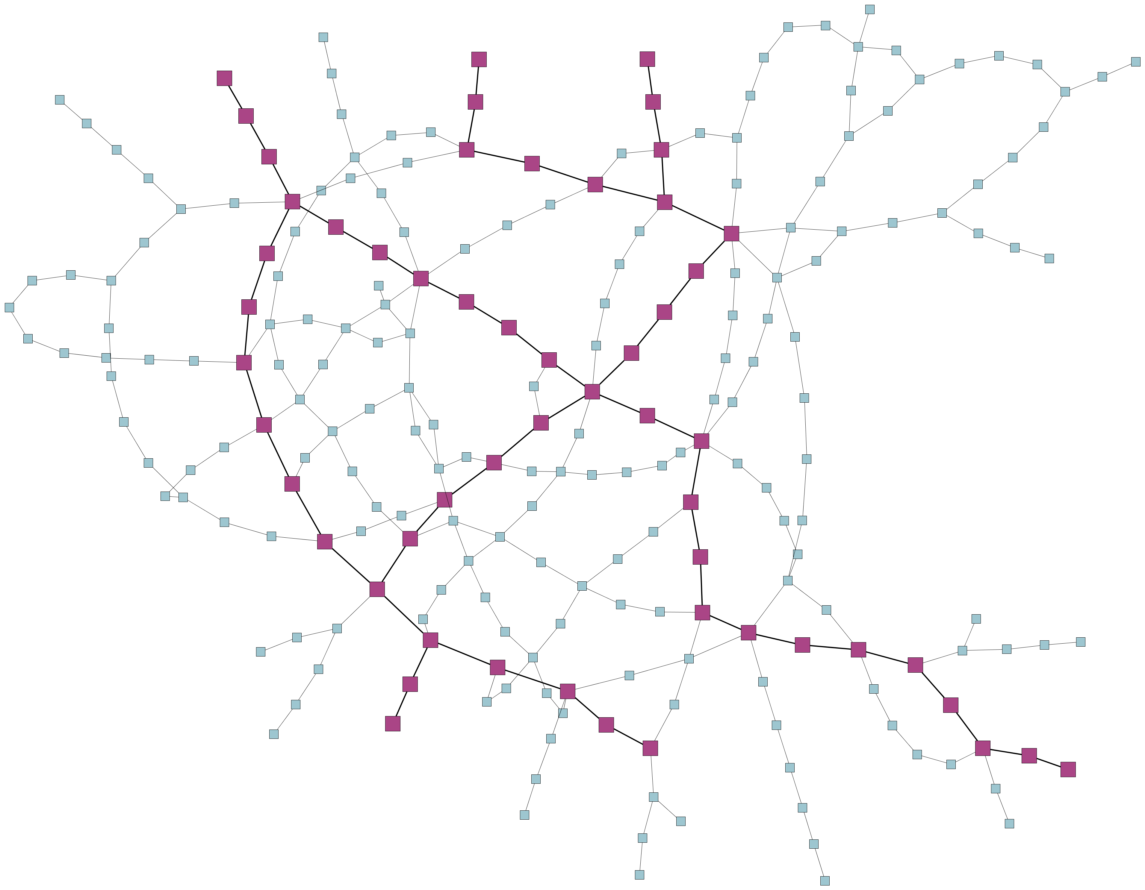
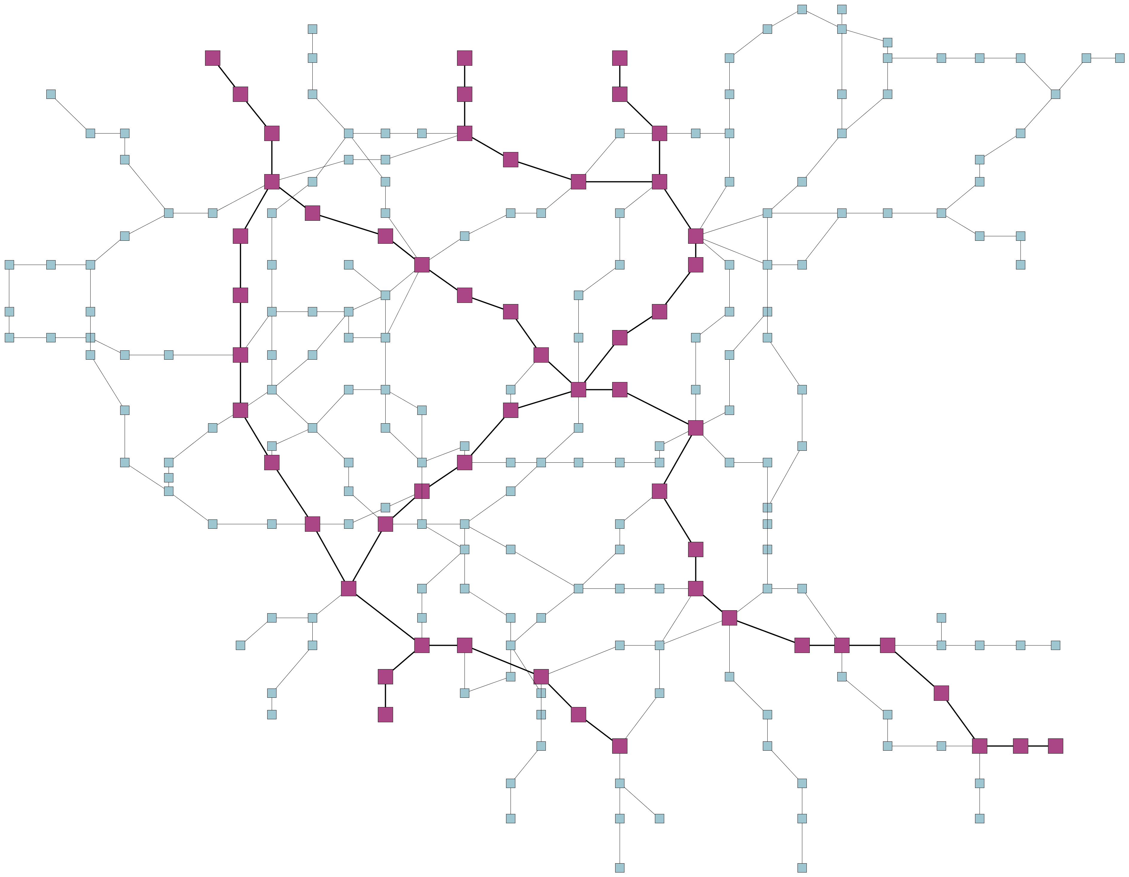
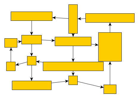
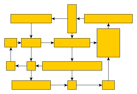
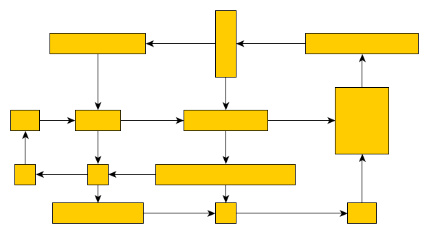
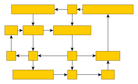
The LineWrappingStage is a layout stage that can be used to line-wrap or column-wrap a graph layout. Line-wrapping arranges the graph into horizontal lines, while column-wrapping arranges it into vertical columns. It allows you to specify a desired aspect ratio for the wrapped layout or a fixed width (height) for the lines (columns).
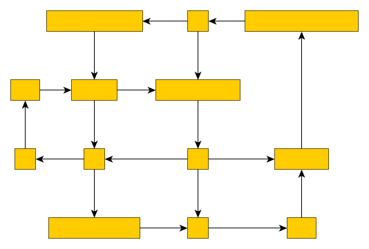
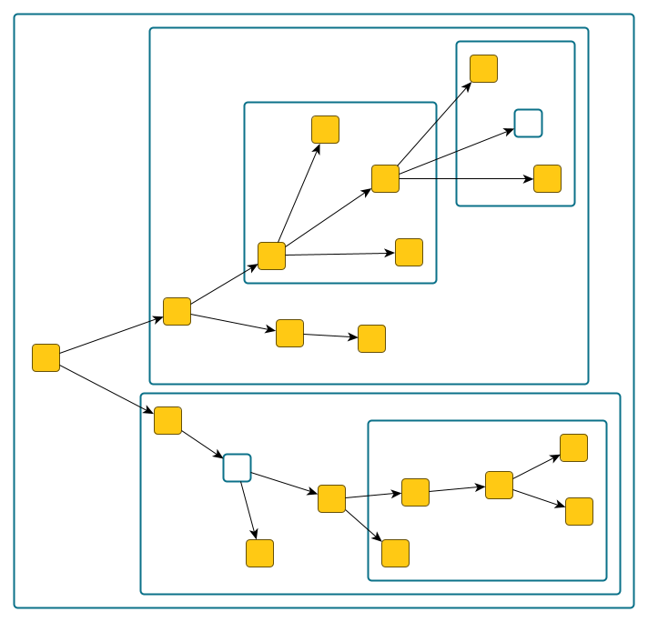
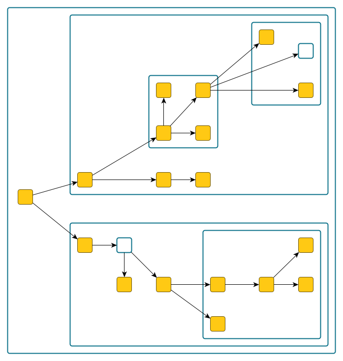
The LineWrappingStage is most commonly used with hierarchical layouts. Hierarchical layout before and after line-wrapping shows a hierarchical layout that has been line-wrapped to achieve a desired aspect ratio.


Using LineWrappingStage with hierarchical layout shows how the LineWrappingStage class can be used to wrap hierarchical top-to-bottom layouts.
graph.applyLayout(
  new LineWrappingStage({
    columnMode: true,
    mirror: false,
    coreLayout: new HierarchicalLayout()
  })
)LineWrappingStage provides a set of options that influence its behavior.
- columnMode
-
Specifies whether the graph layout should be column-wrapped instead of line-wrapped. If enabled, the layout will be arranged in columns. Otherwise, it will be arranged in lines.
- spacing
-
Defines the spacing between adjacent lines (columns) in the line-wrapped (column-wrapped) graph layout.
- edgeSpacing
-
Defines the spacing between adjacent edge paths that connect consecutive lines (columns) in the line-wrapped (column-wrapped) graph layout.
- mirror
-
Specifies whether the lines (columns) of the line-wrapped (column-wrapped) graph layout should be arranged in an alternating (mirrored) manner. Every second line (column) goes from right to left (bottom to top) instead of left to right (top to bottom).
- fixedWidthLineBreaks
-
Specifies whether the lines (columns) of the line-wrapped (column-wrapped) graph layout should use a pre-set width (height) defined by fixedWidth. If enabled, the layout will use the fixed width/height. Otherwise, the width/height is automatically determined to reach the target aspect ratio.
- fixedWidth
-
Defines the width (height) that should be used for the lines (columns) of the line-wrapped (column-wrapped) graph layout. This setting only has an effect if pre-set line width (column height) is enabled through fixedWidthLineBreaks.
- targetRatio
-
Defines the desired aspect ratio for the line-wrapped (column-wrapped) graph layout. This setting only has an effect if automatic line width (column height) is enabled.
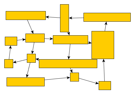
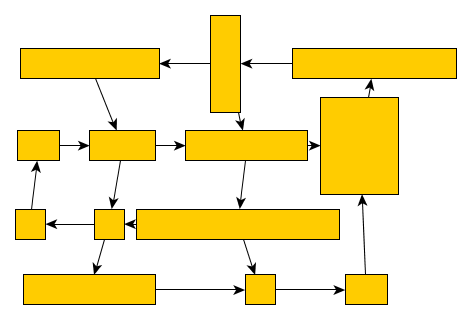
Alignment Stage
The class AlignmentStage is a layout stage that automatically aligns nodes on vertical and horizontal lines. The stage minimizes the number of lines used, while ensuring that the nodes' position changes are limited.
The algorithm operates in two phases. In the first phase, the nodes are partitioned into disjoint sets for both the x-dimension and the y-dimension. During this phase, the nodes are aligned to lines whose positions are not yet defined. In the second phase, the positions of these lines, and consequently the positions of their assigned nodes, are determined. The positions are chosen to minimize the overall movement of the nodes.
|
Note
|
The stage is intended to be used as a post-processing step on graphs that are already well-arranged. Although the stage can resolve node overlaps, it is recommended to use it on graph layouts without node overlaps. If necessary, another stage that resolves node overlaps can be applied before this stage (e.g., RemoveOverlapsStage). |
|
|
Basic Properties
- alignmentPolicy
-
The AlignmentStage allows you to specify the direction in which the nodes are snapped. Choosing the x-direction means that the nodes are snapped to vertical grid lines, while choosing the y-direction means that the nodes are snapped to horizontal grid lines. If both axes are chosen, the snapping is done sequentially for the two orientations. See Table Example for the choice of the alignment policy. for an example.
|
|
no node alignment |
y-coordinates are snapped |
|
|
x-coordinates are snapped |
both x- and y-coordinates are snapped |
- snapDistance
-
The snap distance describes the maximum distance between two nodes that can be snapped to the same line. That is, two nodes are aligned on the same line only if the distance between their centers does not exceed the given snap distance in the respective dimension. Therefore, large snap distances produce a more pronounced grid structure but deviate more from the initial layout than small snap distances.
- separateStripes
-
If this property is enabled, the nodes are placed in strictly separated rows and columns. That is, nodes aligned on consecutive lines are geometrically separated by lines. Table Example for separated alignments. (right column) shows an example with separated stripes. The nodes assigned to consecutive horizontal lines are separated by a horizontal line, where the nodes of one grid line are above that horizontal line, and nodes of the other are below. Similarly, the nodes assigned to consecutive vertical grid lines are separated by a vertical line. This gives the visual impression that the nodes are placed in disjoint rows and columns. While enabling this property visually separates nodes, it may reduce the compactness of the layout substantially.
|
|
|
not separated |
separated |
- gridSpacing
-
You can place the generated alignments at regular intervals to produce a grid-like appearance. If this property is set to a value greater than zero, the distance between any two parallel alignment axes is set to a multiple of that value.
|
|
not regular |
regular |
- snapOffsets
-
By default, the nodes are aligned with their centers on common lines. However, depending on the use case, you might want to align other points of the nodes, for example, their top-left corners. To that end, the snap point of a node can be customized through a snap offset. The snap offset is relative to the node’s center and defines a snap point in the interior or on the boundary of a node. If the snap point lies outside of the node, the point is mapped onto the boundary of the node. You can specify the snap offset for each node using the supplemental data that can be conveniently defined via class AlignmentStageData<TNode,TEdge,TNodeLabel,TEdgeLabel>.
Grouped Graphs
The alignment stage can also be applied to grouped graphs. In this case, the alignment stage will be performed on all nodes that are not group nodes or that do not have any children. The alignment of these nodes will conform to the Basic Properties. Group nodes that contain child nodes are not aligned. However, it is ensured that they can be drawn without overlaps.
|
|
Not aligned |
Aligned |
Layout Data
Supplemental layout data for a graph’s items can be specified via the AlignmentStageData<TNode,TEdge,TNodeLabel,TEdgeLabel> class. This data can be created using the createLayoutData factory method. Table Supplemental layout data lists the properties of the layout data.
Providing supplemental layout data is described in detail in Layout Data.
| AlignmentStageData Property | Element Type | Value Type | Description |
|---|---|---|---|
node |
Point |
A Point that specifies the snap point of the node. |
|
node |
Insets |
An Insets object that specifies the margins at each side of a node. |
|
Specifies a LayoutGrid for the alignment stage to consider. |
|||
layoutGridData.grid |
graph |
Specifies the partition grid structure for the graph. Can also be defined using the rowIndices and columnIndices properties. |
|
layoutGridData.layoutGridCellDescriptors |
node |
Specifies the layout grid cell descriptor for a node. Alternatively, cell indices for a node can be specified using the rowIndices and columnIndices properties. |
|