Organic Layout
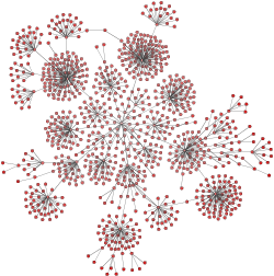
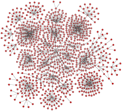
The organic layout style uses the force-directed layout paradigm. When calculating a layout, the nodes are treated as physical objects with mutually repulsive forces, like protons or electrons. The connections between nodes are also treated as physical analogies and are considered springs attached to the pair of nodes. These springs produce repulsive or attractive forces between their end points if they are too short or too long. The layout algorithm simulates these physical forces and rearranges the positions of the nodes in such a way that the sum of the forces emitted by the nodes and the edges reaches a local minimum.
Resulting layouts often expose the inherent symmetric and clustered structure of a graph. They show a well-balanced distribution of nodes and have few edge crossings.
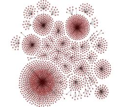
This layout style is well suited for visualizing highly connected backbone regions with attached peripheral ring or star structures. These structurally different regions of a network can be easily identified by looking at a drawing produced by organic layout algorithms.
Application Areas
The organic layout style is a versatile layout algorithm for undirected graphs. It generates clear visualizations of complex networks and is particularly well-suited for application areas such as:
-
Bioinformatics
-
Enterprise networking
-
Knowledge representation
-
System management
-
WWW visualization
-
Mesh visualization
Relevant Classes
Relevant classes for this style lists the relevant classes for the organic layout style.
| Class Name | Description |
|---|---|
Main algorithm. See the description below. |
|
Layout data for the OrganicLayout class. It is used to specify layout options for the individual nodes and edges. Can be created with the factory method createLayoutData |
|
This class provides organic layout in an interactive environment where a user directly manipulates a diagram and updates to the diagram’s layout are calculated continuously. See the description of this class in Interactive Organic Layout. |
|
Layout data for the InteractiveOrganicLayout class. See basic options of InteractiveOrganicLayout. |
Class OrganicLayout is an organic layout provider that supports both complete re-layout of a given diagram and incremental layout where only a subset of a diagram should be rearranged.
One of the strengths of OrganicLayout is its ability to control the ratio of quality versus running time, as well as its ability to produce organic layouts while guaranteeing the absence of node overlaps. Additionally, OrganicLayout also prevents node label overlaps and keeps minimum distances between nodes.
Basic Options
- defaultPreferredEdgeLength
-
Allows you to specify the default preferred length for all edges. The layout algorithm attempts to arrange the nodes so that the edges have the desired length. To measure edge lengths, the nodes are approximated as disks. The edge length is measured between the edges of the disks corresponding to the edge’s source and target nodes.
To specify the preferred edge length for each edge individually, provide supplemental layout data, for example, using the property OrganicLayoutData.preferredEdgeLengths. Note that if an individual preferred edge length is not specified, the default preferred edge length is used.
- edgeLabelPlacement
-
By default, edge labels are placed automatically using the generic labeling support, as described in Generic Labeling. This behavior can be changed to ignore the edge labels or to use an integrated edge labeling algorithm.
- nodeLabelPlacement
-
By default, the OrganicLayout considers the node labels when arranging the nodes, but does not move them relative to their owner nodes. This behavior can be changed to ignore node labels completely, which may lead to more compact layouts. Alternatively, the node labels may be placed in a post-processing step by an independent labeling algorithm.
- allowNodeOverlaps
-
Specifies whether nodes are allowed to overlap. If this feature is disabled (which is the default), the "Minimum Node Distance" will be used to arrange the nodes so that the given distance is maintained.
- defaultMinimumNodeDistance
-
The minimum distance between nodes, which is used if node overlaps are not allowed.
By default, the organic layout guarantees that no nodes or node labels overlap, even for very dense graphs. This behavior can be controlled using the "Allow Node Overlaps" and "Node Label Placement" properties.
Additionally, using the "Minimum Node Distance" property, you can specify a minimum distance between nodes. This guarantees a certain amount of space around each node that is not occupied by other nodes.
- chainRecognition
-
If this property is enabled, the OrganicLayout adaptively straightens chains, i.e., it straightens paths of degree-2 nodes. More precisely, if the nodes of a chain lie almost on a common straight line after the physical forces are applied, the positions of these nodes are adjusted so they are aligned on a straight line. The orientation of the line, as well as the order and distances of the nodes, is determined automatically.
- circleRecognition
-
If this property is enabled, the OrganicLayout detects cycles in the graph whose nodes almost lie on a geometric circle. For each of these cycles, the layout algorithm rearranges the nodes so that they lie exactly on a geometric circle. The radius is determined automatically. Currently, only cycles are supported that are connected to the remaining graph by at most one edge and that do not have any chord edges (edges between nodes on the cycle that are not themselves edges of the cycle).
- compactnessFactor
-
Adjusting this value can lead to different layouts. For small values, the resulting layout will use a lot of space, and nodes tend to be far away from each other. Values around 0.5 lead to evenly distributed nodes, whereas values near 1.0 produce highly compact layouts.
Layout results when using different compactness settings shows the results of layout calculations using different compactness values.
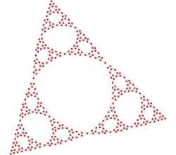
- shapeConstraint
-
Allows you to impose "shape constraints" on the result of the layout calculation. The layout result can be specified to fit into a (simple) geometric shape, like a rectangle or a circle. Also, the layout result can be restricted to a rectangle with a specified aspect ratio.
The class ShapeConstraint serves as a factory to create predefined shape constraints that can be used in conjunction with this property.
The OrganicLayout can choose between different strategies, combinations, and configurations of related algorithms to control the running time versus the layout quality.
- qualityTimeRatio
-
This setting can be used to adjust the trade-off between quality and running time of the layout algorithm. Using small values, it is possible to produce acceptable layouts for huge graphs (thousands of nodes) within seconds. Setting this value to greater values leads to high-quality layouts, which may take longer (up to a few minutes for hundreds of nodes). For large graph structures (hundreds and thousands of nodes), it is advisable to begin with smaller values and gradually increase them.
- stopDuration
-
Sets the duration the layout process runs before stopping gracefully. The real runtime may exceed the specified stop duration since the layout process needs to find a valid solution. If the stop duration is reached, the quality of the layout may not be optimal. Increasing this value increases the likelihood of an optimal layout.
- deterministic
-
Specifies whether the layout process should be deterministic. In deterministic mode, the layout algorithm produces identical results for identical input graphs and identical settings, provided that the stop duration is not restrictive.
Labeling
Edge labels can be placed automatically using the generic labeling support as described in Generic Labeling, which is available with all yFiles layout algorithms. Additionally, OrganicLayout can be set up to take node labels into account during layout. Node labels do not need to be placed, but instead their size needs to be considered for the placement of adjacent graph elements. Taking node labels into consideration during layout calculation guarantees that they will not overlap nodes in the diagram.
Node label awareness is enabled using the "Consider Node Labels" property. See the description of the options in Basic Options.
Grouped Graphs
OrganicLayout directly supports the layout of grouped graphs. The algorithm calculates both the positions and dimensions of group nodes.
You can fine-tune how group nodes are handled during layout calculation by specifying a GroupNodeHandlingPolicy for nodes as supplemental layout data via the property OrganicLayoutData.scope.groupNodeHandlingPolicies. The following constants are available to instruct the algorithm how to treat a specific group node:
- FREE
-
The layout algorithm processes the contents of the group node. The algorithm also determines the group node’s size and position.
- FIX_CONTENTS
-
The algorithm determines the size and position of the group node. The contents of the group node are not processed by the algorithm but are moved with the group node.
- FIX_BOUNDS
-
The layout algorithm processes the contents of the group node, but the original bounds of the group node do not change.
Note that when used with layout tables, only the first constant is supported.
|
Tip
|
Using the FIX_CONTENTS or FIX_BOUNDS constant for group nodes also enables additional incremental layout behavior specifically for group nodes. |
Advanced size requirements for group nodes can be handled by registering a custom ILayoutGroupBoundsCalculator implementation through the property groupBoundsCalculator.
Incremental Layout
OrganicLayout supports different kinds of incremental layout strategies through the Scope feature. The settings related to this feature are combined in the sub-data OrganicLayoutData.scope.
By default, OrganicLayout re-computes the entire layout of a given graph; that is, it performs a non-incremental layout. When only a subset of the graph should be rearranged, you can specify the desired subset via the property nodes. The specified subset of nodes is then arranged incrementally.
It is also possible to specify that nodes close to the nodes in the subset should be rearranged as well by defining scope modes via the property scopeModes. Even though the scope modes may be combined with explicitly defining a subset of nodes, it is usually simpler to use one or the other, but not both. The following scope modes are available.
- AFFECTED
-
The node is arranged by the layout algorithm.
- FIXED
-
The node is not arranged by the layout algorithm unless it is affected by nodes close to it.
- INCLUDE_EXTENDED_NEIGHBORHOOD
-
The node is arranged by the layout algorithm. Nodes that are structurally close to this node may also be moved.
- INCLUDE_CLOSE_NODES
-
The node is arranged by the layout algorithm. Nodes that are geometrically close to this node may also be moved.
Incremental layout of augmented graph shows the resulting diagrams for different scope settings for the initial (augmented) graph from Initial graph and an augmentation. Only (or mostly) the nodes from the specified subset get arranged by OrganicLayout. The other nodes keep their positions.
|
Note
|
When only a subset of nodes should be rearranged and the "Allow Node Overlaps" property is enabled, unselected nodes may be moved to resolve node overlaps. |
You can achieve further incremental layout behavior specifically for group nodes through specific group node handling policies; that is, the property OrganicLayoutData.scope.groupNodeHandlingPolicies. See also the corresponding description for layout data in Grouped Graphs.
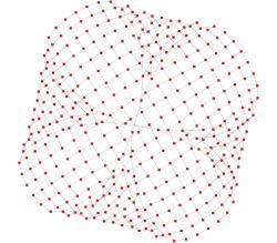
Tables
OrganicLayout supports layout grids (class LayoutGrid). This layout type arranges nodes within a table-like grid structure. Each standard node is placed into a single cell, and the contents of group nodes are placed into the same cell as the group node itself. See Tables and Swimlanes for information on how to set up partitioned layouts.
Grid layout as calculated by OrganicLayout shows an example of a grid layout calculated by OrganicLayout. The table’s visual representation is rendered by a group node that uses the TableNodeStyle node style.
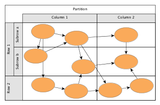
To configure a grid layout with OrganicLayout, use the layout data property OrganicLayoutData.layoutGridData.
OrganicLayout supports the following configuration options for layout grids regarding standard and group nodes. The layout algorithm places a standard node based on its associated grid cell descriptor:
- None
-
The node is placed in a suitable cell within the layout grid structure.
- Single cell
-
The node is placed in the specified cell.
The layout algorithm places a group node such that:
- None or single cell
-
It encompasses all its contained nodes. If the contained nodes have grid cell descriptors associated with them, the grid cell descriptor of the group node is ignored.
- Range of cells
-
Its boundary corresponds to the smallest rectangle encompassing the specified range of cells, regardless of the cells occupied by its contained nodes.
|
Important
|
A node contained in a group node can have either no partition cell descriptor associated with it (none) or a single cell partition cell descriptor configuration. All nodes with the latter, however, need to use the same partition cell descriptor configuration. |
In conjunction with the group node handling option, grid layout calculation does not support group nodes that are associated with group node handling policies other than FREE.
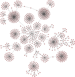
Substructures
The organic layout algorithm can identify regular substructures in a graph, such as:
-
chains
-
stars
-
cycles
-
parallel structures
-
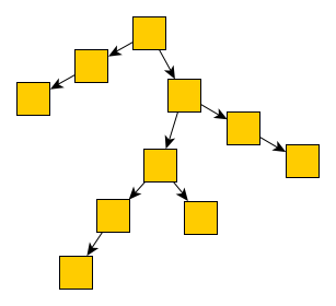
trees
-
groups
It arranges these substructures in an optimized way based on the type of substructure. This makes them easily recognizable in the resulting layout.
For example, the diagram in the following figure has star substructures of different sizes, a chain, a cycle, a parallel substructure, a group substructure and a tree.


To enable the identification and arrangement of regular substructures, the following properties are available:
- chainSubstructureStyle
- cycleSubstructureStyle
- parallelSubstructureStyle
- starSubstructureStyle
- treeSubstructureStyle
- groupSubstructureStyle
-
These properties enable or disable the logic for finding specific substructures and configure the layout style for each type of substructure.
|
Tip
|
To define the minimum number of nodes a substructure must contain to be handled as such, a property regarding each style is available (e.g., for chains, chainSubstructureSize). |
As an option, the logic to identify the regular substructures can take node types into account. A substructure can only contain nodes of the same type. The types can be specified via the layout data property nodeTypes.
Another option that influences the detection of substructures is the edge directedness. This means that within a substructure all edges need to have the same direction. To enable this option, define supplemental layout data that specifies the directedness for edges, via the OrganicLayoutData.edgeDirectedness property.
An edge can be marked using one of the following directedness values:
-
0 denotes a regular, i.e., undirected edge
-
1 denotes an edge that should be oriented from source to target
-
-1 denotes an edge that should be oriented from target to source
Note that this support for edge directedness is only provided by the logic that identifies the regular substructures in
a graph and is only taken into account in conjunction with substructure layout.
By default, all edges are assumed to have a directedness value of 0.
For the layout of stars (style separated radial only) and parallel substructures, edge groups that are specified for the edge ends at the substructure’s root node or its common end nodes will automatically be observed. Edges that belong to the same group at an end will be routed in a bus-style manner with an additional bend inserted into the edge path.
The following figure shows the resulting layout of a parallel substructure with one edge group at each of the end nodes:


The general setup for edge groups is described in section Edge and Port Grouping.
You can configure the substructure layout component of OrganicLayout via supplemental layout data such as properties edgeDirectedness, substructureSourceGroupIds, and substructureTargetGroupIds.
Nesting of Substructures
Some substructures can be nested inside others. This nesting can highlight the connections between them and may be useful in certain cases. However, nesting can make the overall layout less compact because a nested structure often increases the size of the outer structure. This is especially noticeable if the other elements of the outer structure are much smaller (i.e., the sizes are not uniform).
Nesting is supported by styles with the respective suffix, such as:
Substructures are detected in the following order: groups, cycles, stars, chains, parallel structures, trees. Because of this fixed order, the nesting possibilities are determined. For example, parallel structures cannot be nested at all, and stars may be nested inside chains and parallel structures, but not inside cycles. As a special case, groups do not support nesting in either direction: a group substructure cannot be nested in any other substructure, and no other substructure can be nested in a group.
Node Margins
By default, OrganicLayout supports node margins as soon as they are declared. The layout considers any specified additional padding around nodes. However, due to the straight-line routing of the edges, they can cross through these areas in the resulting diagram.
Node margin overlaps may occur if:
-
option allowNodeOverlaps is enabled
-
only a subset of the nodes are rearranged (see Section Incremental Layout)
You can specify node margins via the layout data property nodeMargins.
Edge Orientation
OrganicLayout supports the definition of edge orientations with respect to the specified layout orientation. For an edge, a positive orientation means that the edge should have the same orientation as the layout orientation, while a negative orientation means that it should have the opposite orientation. For example, if the orientation of the layout is from left to right, a positive orientation of an edge means that it should also go from left to right.
|
|
By default, the orientation of the edges is undefined, which means that the edges do not have a common flow direction.
You can specify the orientation of edges by means of supplemental layout data via the edgeOrientation property. A negative value is interpreted as a negative orientation, a positive value is interpreted as a positive orientation, and 0 is interpreted as an undefined orientation.
Edge Lengths
Besides the preferred edge length, which serves as the main parameter for controlling the length of edges, OrganicLayout also supports defining minimum edge lengths. You can use this feature, for example, to ensure sufficient space along an edge for placing a label without causing overlaps.
You can specify edge lengths using supplemental layout data via the minimumEdgeLengths property.
Constraints
OrganicLayout supports different types of constraints that restrict the placement of the graph’s nodes. You can specify these constraints using supplemental layout data via the constraints property. The OrganicLayout enforces the specified constraints when it applies the physical forces to the nodes.
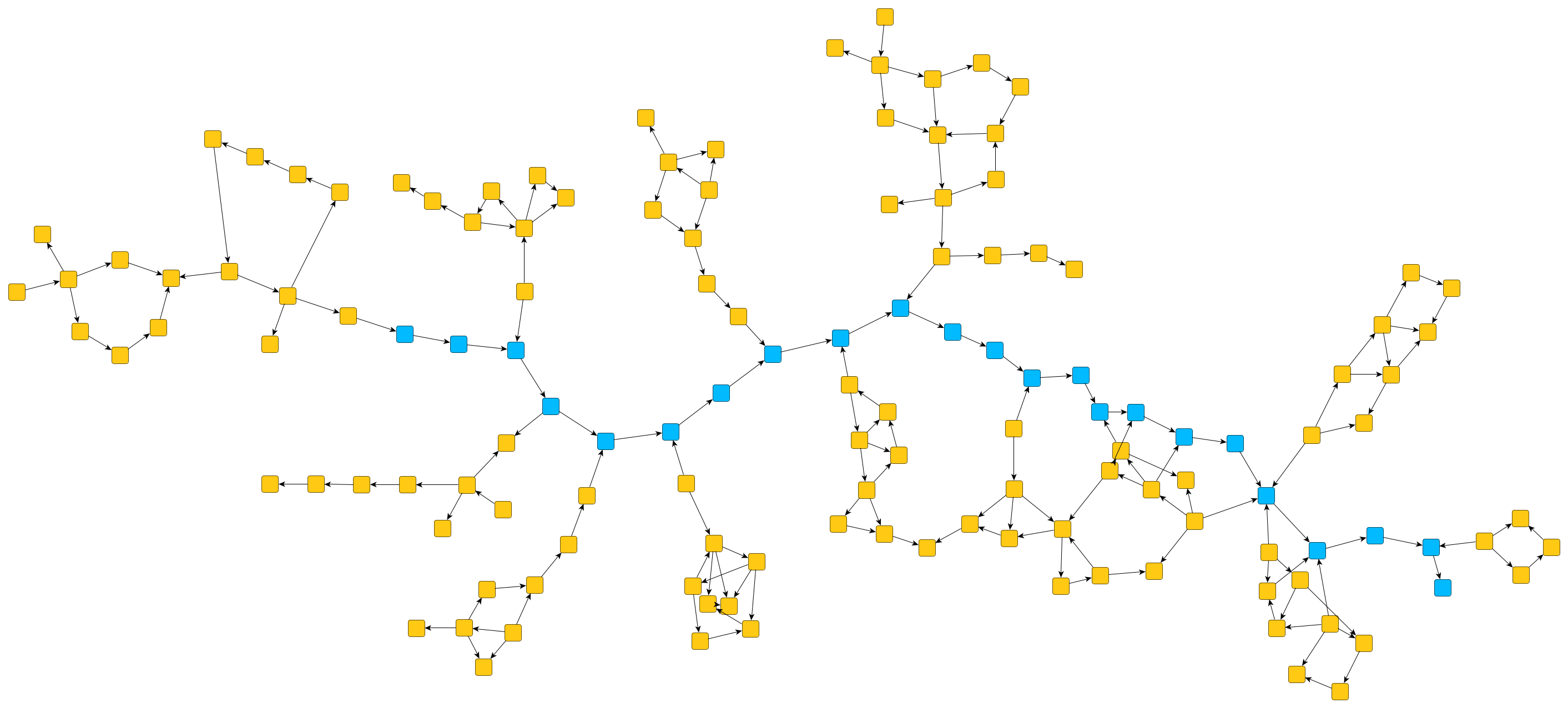
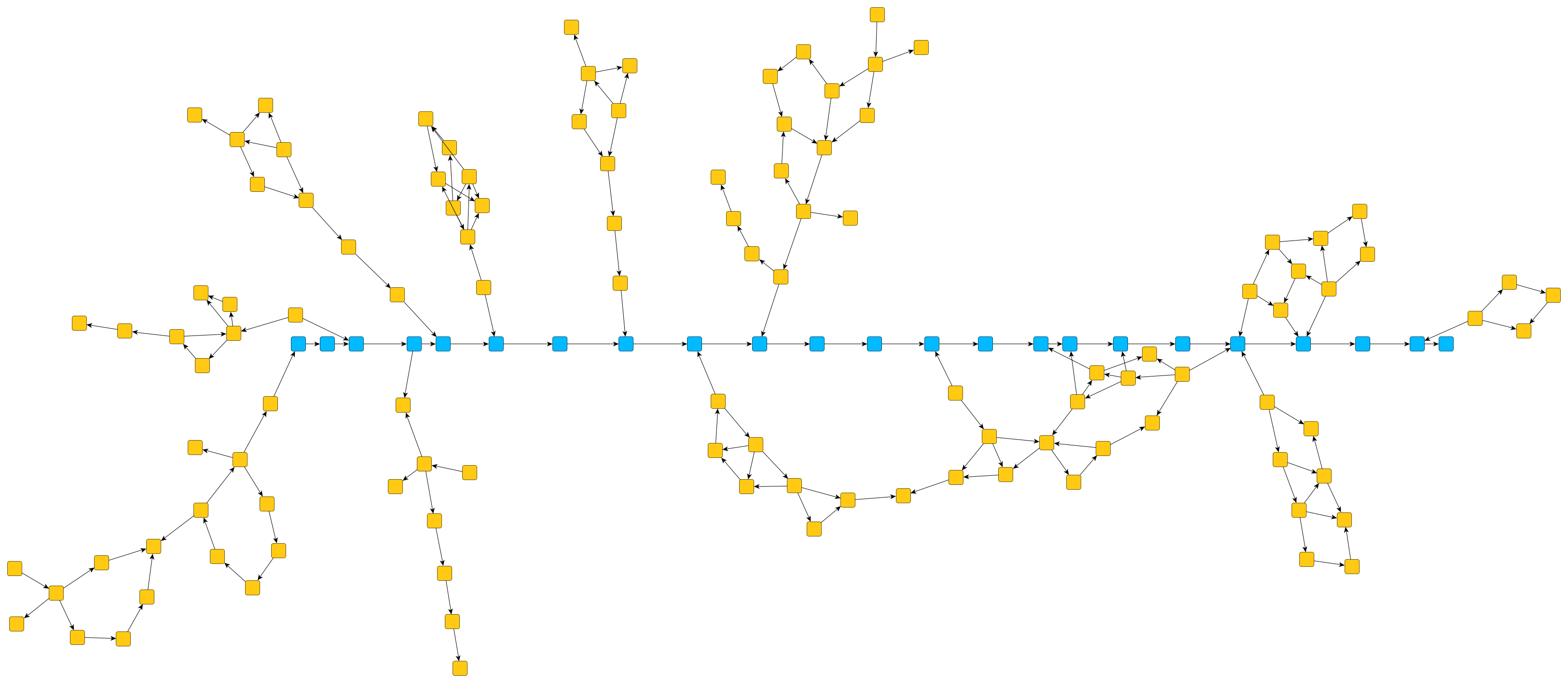
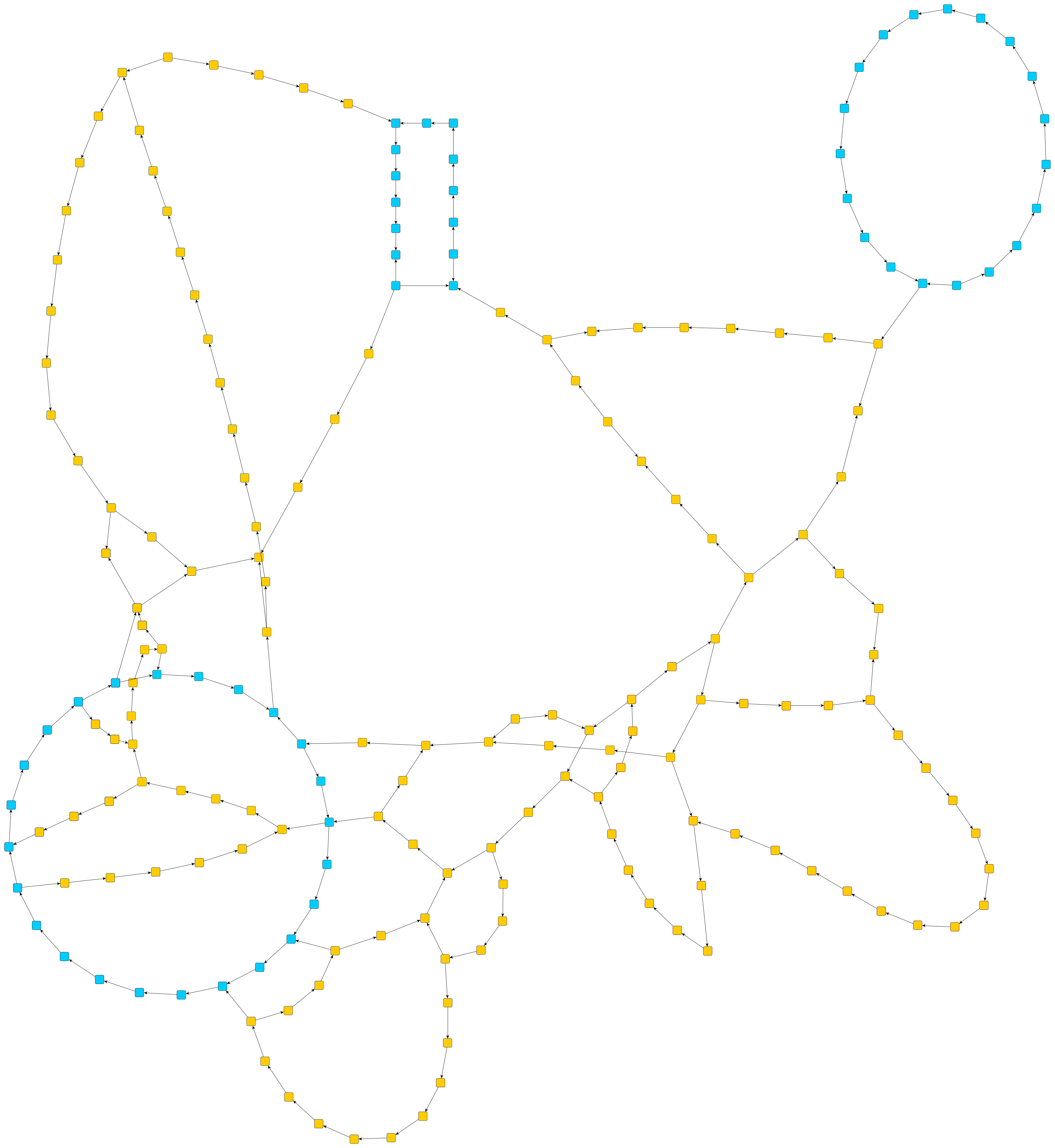
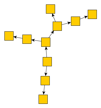
-
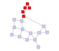
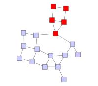
Example 1 - Alignment of nodes. This type of constraint forces the specified nodes to lie on a common line. You can specify whether this line should be horizontal or vertical. This constraint is particularly useful for emphasizing paths in layouts. The first figure above shows a graph layout without any constraints, while the second figure shows the same layout, but this time the blue nodes have been forced to lie on a horizontal line, geometrically emphasizing that they lie on a path.
-
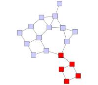
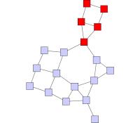
Example 2 - Geometric shapes. This type of constraint forces the specified nodes to lie on a common axis-aligned rectangle or ellipse. The third figure shows an example in which multiple subsets of nodes are forced to be placed on rectangles and ellipses. Apart from the nodes, you can also specify the aspect ratio of the geometric shapes. For example, defining an aspect ratio of 1 results in a square or circle. Similar to constraints aligning nodes, this type of constraint can be used to emphasize cycles in the graph layout.
When specifying constraints, keep in mind that these constraints can easily oppose the physical forces applied to the nodes. It is therefore recommended to use the constraints to visually emphasize structures that are also respected by the physical forces. For example, if nodes almost lie on a circle when using the OrganicLayout without constraints, forcing them onto a circle opposes the physical forces only a little. Hence, the constrained placement of these nodes will blend in seamlessly with the remaining layout.
The constraints have the following technical restrictions:
-
Graphs with groups. Currently, only constraints for nodes that lie in the same group are supported. If two affected nodes lie in different groups, the entire constraint is ignored.
-
Contradicting Constraints. When defining constraints for nodes, it is recommended that the constraints do not contradict each other. Otherwise, the OrganicLayout ignores some constraints so that the remaining constraints do not contradict each other. It is not defined which of the constraints are ignored, and OrganicLayout is free to do this arbitrarily.
Interactive Organic Layout
The class InteractiveOrganicLayout provides organic layouts for use in interactive environments. Its strength is its capability to generate continuous updates to the layout of a graph during calculation. Furthermore, it also allows a user to seemingly simultaneously perform arbitrary modifications to a graph, which are subsequently accounted for in the layout calculation.
|
Important
|
Due to the interactive nature of this layout algorithm, the usual mechanisms to run a layout algorithm are not applicable. |
Among other things, this means that there is no special support for routing of either self-loops or parallel edges, for example. In particular, when a graph contains parallel edges, they will be routed using overlapping edge paths.
Basic Options
Interactive organic layout provides a range of options that influence its behavior. These options can be configured though the properties of the class InteractiveOrganicLayout or its associated layout data class InteractiveOrganicLayoutData. Note that the layout data class requires using an IGraph.
|
Important
|
Once the node and edge handles have been initialized (in particular after the layout process has been started), the properties on the handles need to be used to update the settings. Trying to specify them directly via the properties on InteractiveOrganicLayoutData will have no effect. |
- InteractiveOrganicLayout.stopDuration
-
Sets the duration for which the layout process will run before stopping gracefully. The real runtime may exceed the specified stop duration since the layout process needs to find a valid solution. If the stop duration is reached, the quality of the layout may not be optimal. Increasing the value increases the likeliness of an optimal layout.
After the layout process has finished or the time specified using Stop Duration is spent, InteractiveOrganicLayout will sleep, i.e., it has to be awakened before another layout process can be invoked (see also the description of running/sleeping state of InteractiveOrganicLayout).
- InteractiveOrganicLayout.preferredNodeDistance
-
The preferred node distance which will be used to calculate the layout. The layout algorithm tries to arrange the nodes in such a way that the desired distance is complied with.
- InteractiveOrganicLayout.defaultPreferredEdgeLength
- InteractiveOrganicLayoutData.preferredEdgeLengths
- InteractiveOrganicEdgeHandle.preferredEdgeLength
-
Properties for both the default preferred edge length and individual preferred edge lengths. The layout algorithm tries to arrange the nodes in such a way that the edges have the desired edge length. The edge length is measured from node border to node border.
- InteractiveOrganicLayout.qualityTimeRatio
-
This setting can be used to adjust the quality of the layout calculated by the layout algorithm. Small values lead to short running times, while greater values result in better quality. For large graph structures (hundreds and thousands of nodes) it is advisable to begin with smaller values and to gradually increase them.
- InteractiveOrganicLayout.shapeConstraint
-
Allows to impose so-called "shape constraints" on the result of the layout calculation. More precisely, the layout result can be specified to fit into a (simple) geometric shape, like a rectangle or a circle. Also, the layout result can be restricted to a rectangle with a specified aspect ratio.
The class ShapeConstraint serves as a factory to create predefined shape constraints that can be used in conjunction with this property.
General Usage
In the single-threaded JavaScript execution environment, InteractiveOrganicLayout is designed to be used in a cooperative setup where the layout algorithm does its calculations in defined time slices after which it yields back control to the application. This enables an application that presents a graphical user interface (GUI) to the user to remain nearly fully interactive while the layout algorithm, at least perceived simultaneously, performs its calculations. This setup also enables modifications to the graph seemingly simultaneous to the layout calculation.
Setup
The InteractiveOrganicLayout provides the method startLayout to start the layout process for a given period of time as show in the example below. Afterward, the layout process can be continued (again for a given period of time) using the method continueLayout.
// Note that the given graph is of type IGraph.
// Layout algorithms require an instance of a LayoutGraph, so we use LayoutGraphAdapter to
// create a structural copy of the original graph.
const adapter = new LayoutGraphAdapter(graph)

// Create an appropriate layout data instance for additional data that needs to be available to
// the layout algorithm.
const layoutData = new InteractiveOrganicLayoutData()
adapter.applyLayoutData(layoutData)

// Configure and start the layout algorithm
const organicLayout = this.getMyInteractiveOrganicLayout()
organicLayout.startLayout(adapter.layoutGraph, 100)Life Cycle
The interactive organic layout algorithm can be in either of three states: running, sleeping, or stopped. While in the running state, the algorithm operates within the specified stop duration, continually generating "intermediate" layouts for the given graph. In the sleeping state, the algorithm does nothing, but is still "alive." In contrast, in the stopped state, the algorithm is terminated. State diagram for InteractiveOrganicLayout depicts the states and the possible state transitions of InteractiveOrganicLayout.

The following properties can be used to query the current state of an InteractiveOrganicLayout instance, change its state, and set the stop duration. Note that when an instance is changed from "sleeping" to "running" state, the stop duration is again fully available.
- running
- sleeping
- stopped
-
Properties to query the algorithm’s current state.
- wakeUp(): void
- startLayout(graph: LayoutGraph, duration: TimeSpan): void
- stopLayout(): void
-
Methods to change the current state.
- stopDuration
-
Determines the duration until the algorithm shall terminate gracefully when in "running" state.
Handles
The concurrent setup as used with InteractiveOrganicLayout means that the layout process does not return a single result by itself, but instead continuously generates "intermediate" results as long as it is in "running" state. Handles of type InteractiveOrganicNodeHandle and InteractiveOrganicEdgeHandle allow to interact with these intermediate results. They provide methods to poll the current intermediate values such as the positions of the nodes, which may be used to show a live animation of the layout process (see Section Polling for Results). Moreover, they allow to change the intermediate values, e.g. to move a node to a different position, which may be useful when handling user interaction during the layout process (see Section Interaction).
When using InteractiveOrganicLayoutData, mappings from nodes and edges to their handles is maintained automatically. They can be accessed via properties nodeHandles and edgeHandles
Polling for Results
The current intermediate results of the InteractiveOrganicLayout can be accessed through handles. These handles can be polled by a user at any time and be used as continuous updates to the layout of a graph.
The following methods allow to easily poll either the current coordinates of single nodes or commit all current positions of nodes to the original graph at once:
- InteractiveOrganicNodeHandle.getCenter(): Point
-
Retrieve the current center coordinates of a single node from InteractiveOrganicLayout’s data structures.
- InteractiveOrganicLayoutData.updateNodeCenters(graph: IGraph, max: number, ratio: number, minMovement: number): number
-
Updates all node locations with the coordinates from InteractiveOrganicLayout’s data structures.
A convenient way to assign the "intermediate" results in a continuous fashion to the original graph is outlined in Starting an animator that updates the node positions. It uses an Animator that runs indefinitely and updates the node positions in each frame.
// Create and start an infinite animation. Each animation step will
// continue the layout calculation and poll the given organic layout data
// to update the node positions in the original graph.
const animator = new Animator(graphComponent)
animator.autoInvalidation = false
animator.allowUserInteraction = true

animator.animate(() => {
  // Let the layout calculation run for a short amount of time ...
  organicLayout.continueLayout(100)

  // ... and repaint the displayed graph if any node locations have changed.
  if (layoutData!.updateNodeCenters(graph) > 0) {
    graphComponent.updateVisual()
  }
}, TimeSpan.MAX_VALUE)Interaction
The interactive organic layout algorithm allows users to seemingly simultaneously modify node positions and other node-related parameters during a layout calculation. The interaction is facilitated trough methods on the node and edge handles. These methods can be used to update InteractiveOrganicLayout’s data structures with new node positions, and also to specify further node-related parameters such as the size of a node or its inertia:
- setCenter(x: number, y: number): void
-
Set the current center coordinate(s) of a single node in InteractiveOrganicLayout’s data structures.
- InteractiveOrganicNodeHandle.inertia
- InteractiveOrganicNodeHandle.radius
-
Inertia and radius parameters used by InteractiveOrganicLayout.
- InteractiveOrganicEdgeHandle.preferredEdgeLength
-
Specifies the preferred edge length for an individual edge.
To support arbitrary structural modifications to the original graph, i.e., adding or removing nodes and/or edges, the following steps can be used.
-
Stop the current layout process (using methods stopLayout).
-
Optionally, increase the stress of the nodes to make them move faster in the following layout calculations.
-
Restart the layout process (as described in Section Setup).
The following snippet shows how to support structural modification while animating the layout process.
const layoutData = new InteractiveOrganicLayoutData()

const animator = new Animator(graphComponent)
animator.autoInvalidation = false
animator.allowUserInteraction = true

void animator.animate(() => {
  // If the structure of the original graph has changed, i.e., a node or an edge has been
  // added or removed, we have to recreate the layout graph and layout algorithm instances.
  if (this.needsStructureUpdate) {
    this.needsStructureUpdate = false

    // Stop the previous layout calculation, if it is still running.
    organicLayout.stopLayout()

    // If edges have been added or removed, the stress of the corresponding source and target
    // nodes should be increased. Otherwise, the algorithm will not recalculate the locations
    // of those nodes.
    for (const node of this.nodesToStimulate) {
      const handle = layoutData.nodeHandles.get(node)!
      handle.stress = Math.max(handle.stress, 0.5)
    }

    // Re-create the adapter and re-start the layout calculation.
    const adapter = new LayoutGraphAdapter(graph)
    adapter.initialize()

    // Be sure to add the existing layout data instance to the new LayoutGraphAdapter.
    adapter.applyLayoutData(layoutData)

    // Create and configure a new instance of InteractiveOrganicLayout ...
    organicLayout = new InteractiveOrganicLayout()
    // ... and resume the layout calculation.
    organicLayout.startLayout(adapter.layoutGraph, 100)
  } else {
    // Let the layout calculation run for a short amount of time ...
    organicLayout.continueLayout(100)
  }

  // ... and repaint the displayed graph if any node locations have changed.
  if (layoutData!.updateNodeCenters(graph) > 0) {
    graphComponent.updateVisual()
  }
}, TimeSpan.MAX_VALUE)|
Important
|
To avoid race conditions and synchronization problems when structural changes to the graph are allowed, it is strongly recommended to provide InteractiveOrganicLayout a copy of the original graph. When translating an IGraph to a LayoutGraph using a LayoutGraphAdapter as described in Section Setup, this is handled automatically. |
Tutorial Demo Code
Tutorial demo application Interactive Organic Layout shows how to use the layout functionality of class InteractiveOrganicLayout in an interactive environment where the user can "live"-drag nodes and freely modify the graph structure.