Clear and Fill Area Layout
Class ClearAreaLayout is a layout algorithm that clears a user-specified area in a given input graph layout. It moves elements that intersect this area, while trying to minimize the changes to the graph’s original layout.
Class FillAreaLayout is a counterpart to ClearAreaLayout and tries to fill a user-specified area by moving elements towards it.
Both clearing and filling an area have several practical applications. Some examples are:
-
It is possible to add a new node or a whole subgraph component to an existing graph layout at a specific location and use ClearAreaLayout to ensure enough space exists, preventing overlaps between the new component’s elements and the existing nodes (see areaNodes). This use case is showcased in the demo application Node Overlap Avoiding.
-
When removing nodes or subgraph components from a given graph layout, FillAreaLayout can be applied to reduce the whitespace created by the removal operation.
-
Consider nodes that grow in size, which requires clearing an area as well. For instance, a folder node might be expanded and converted to a larger group node, thus requiring more space. Analogously, folding a group node is a possible use case for FillAreaLayout. See the Folding With Layout.
-
Keeping a user-defined rectangular area free of graph elements, as shown in the demos Clear Rectangle Area and Clear Marquee Area.
|
Note
|
The result produced by FillAreaLayout is not the exact inverse of that of ClearAreaLayout. That is, applying both algorithms successively using the same area does not necessarily yield the original layout. Furthermore, FillAreaLayout does not guarantee that the area is filled with elements after calling the algorithm. |
| Class Name | Description |
|---|---|
The algorithm that clears a rectangular area of all other items |
|
Layout data settings for the ClearAreaLayout class. Can be created with factory method createLayoutData |
|
The algorithm that tries to fill a rectangular area |
|
Layout data settings for the FillAreaLayout class. Can be created with factory method createLayoutData |
Input
Both algorithms, ClearAreaLayout and FillAreaLayout, assume that the input graph already has a suitable layout that should be maintained.
Both algorithms allow you to define a rectangle that specifies the area to be cleared or filled. For more information, see the ClearAreaLayout.area and FillAreaLayout.area properties.
ClearAreaLayout also allows you to provide an array of type BorderLine that specifies the outline that must be cleared. This allows describing more complex shapes, with a BorderLine for each of the four sides of the area. For more information, see the areaOutline property.
By using the corresponding layout data class ClearAreaLayoutData, two more ways to specify the area are available, as described in the following sections. You can create the layout data class with the factory method createLayoutData.
Area defined by a set of nodes (AreaNodes)
You can specify a set of nodes that define the area to be cleared using the areaNodes property.
The clear area will be precisely defined by the current locations of these nodes, including the edges connecting them. After the layout is applied, no other elements will intersect with this area. The nodes in this set remain fixed in their positions.
This type of input is useful, for example, if a subset of nodes has been moved to new locations or if multiple new nodes have been added to the diagram.
Area defined by a single expanded node
The property expandedNode allows you to define a single node for which it is assumed that the size has changed (i.e., was enlarged). Therefore, the area defined by the enlarged bounds of the node must be cleared of any other elements. Specifying the area this way is especially convenient when implementing a folder expansion use-case where a folder node is expanded (revealing its content) and, thus, requires more space. Note that the now visible descendant nodes of the expanded folder are not moved. Of course, it does not have to be a folder node; it can be any node that was enlarged for any reason.
This kind of input is similar to the areaNodes discussed in the previous section, but it expects only a single changed node. It offers an advantage when used in conjunction with properties expandedNodeOriginalBounds and expandedNodeOriginalEdgePaths. These properties provide information about the diagram state before expanding the node. Considering this additional information, the algorithm tries to preserve the mental map of the diagram.
The expandedNodeOriginalBounds are the bounds of the node before the size was changed. The expandedNodeOriginalEdgePaths are the paths of all edges adjacent to the node before the size was changed. This should include edges that now connect to descendants of the expanded folder and connected to the folder only before expansion.
|
Important
|
The ways of specifying the input described in the last two sections are mutually exclusive and may not be used at the same time. |
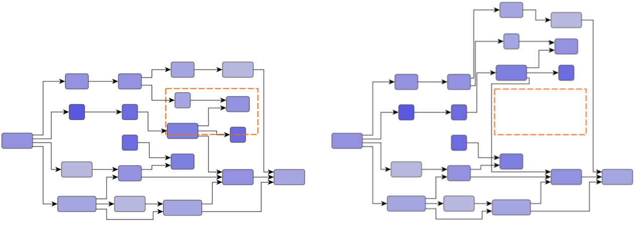
ClearAreaStrategy
clearAreaStrategy specifies the strategy applied for clearing the desired area.
- LOCAL
-
This approach clears the area by trying to minimize the number of moved nodes, changing the layout locally.
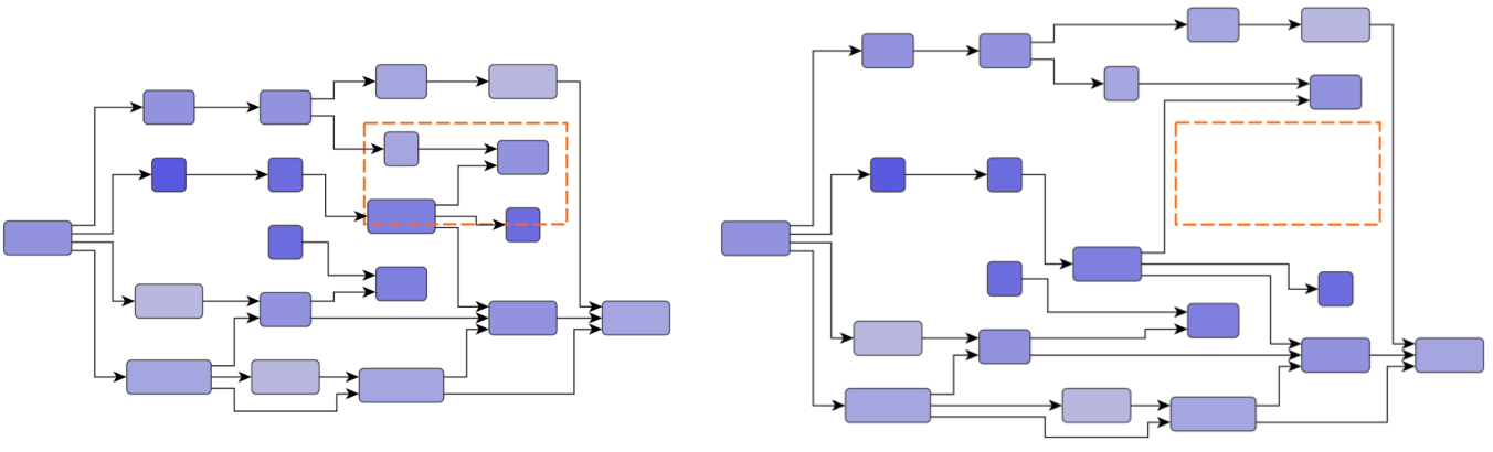
- LOCAL_UNIFORM
-
This approach is very similar to LOCAL but moves all necessary nodes by a uniform offset.
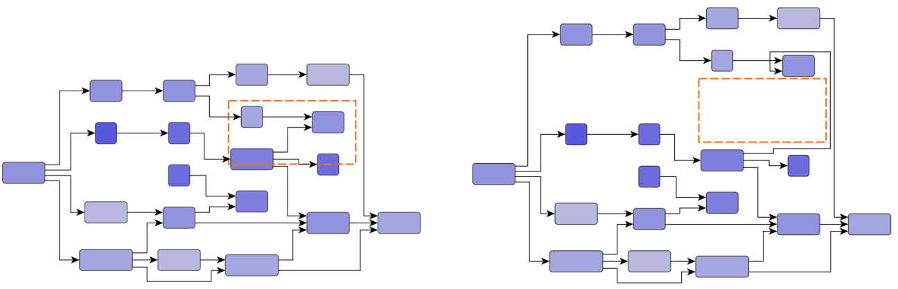
- PRESERVE_SHAPES
-
This approach clears the area while trying to preserve the shape of the existing edge paths. Preserving the shapes means that the direction of the edge segments is not changed, and no new bends are created. The segment lengths may change in order to generate free space.
- PRESERVE_SHAPES_UNIFORM
-
This approach is very similar to PRESERVE_SHAPES but moves all elements by a uniform offset.
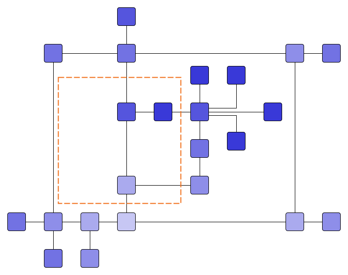
- GLOBAL
-
This approach clears the area by globally partitioning the input into two parts and moving them apart. The division can be vertical or horizontal.
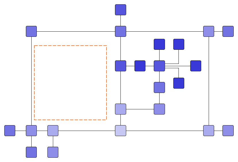
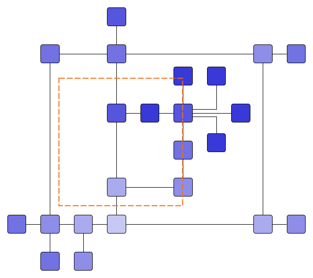
Figure Input (left) and results (right) with different Clear Area Strategies shows the difference between some of the different strategies.