Partial Layout
Related to incremental graph layout, the yFiles library also provides support for partial graph layout. This concept is a perfect fit for incremental scenarios where subsequently added parts should be arranged so that they fit best possible into a given diagram without applying any changes to the already existing layout.
Partial layout supports arranging user-specified parts of a diagram, the so-called partial elements. In a first step, partial elements are combined to form subgraph components. Subsequently, these are arranged and afterwards placed so that the remainder of the diagram, which consists of the so-called fixed elements, is not affected.
Placing a subgraph component predominantly means finding a good position that both meets certain proximity criteria and offers enough space to accommodate the subgraph component.
Compared to incremental layout, the main advantage of partial layout is that it can deal with diagrams of arbitrary origin and layout style, and that the existing layout of the fixed parts of a diagram is left completely unaltered.
Relevant Classes
Class PartialLayout enables layout of user-specified, distinct parts of a diagram without altering the existing layout of the remainder of the diagram. It can be used with flat graphs as well as grouped graphs.
The subset of graph elements that shall be processed (the partial elements) can be specified using layout data for nodes and edges. Note that any edge that is incident to a partial node will implicitly be treated as a partial element, too.
Subgraph Components
The componentAssignmentStrategy property controls which strategy is used to form the subgraph components from the set of partial nodes in the graph. For each of the subgraph components a layout is calculated using the core layout algorithm and it is then placed according to the specified Subgraph Component Placement. Carefully note that independent of the applied strategy, borders of groups and partition cells always split up the components. More precisely, two nodes assigned to different groups or partition cells are always assigned to different subgraph components. Available options are
- CLUSTERING
- A natural clustering algorithm is used to form the subgraph components. Partial nodes of the same cluster are assigned to the same subgraph component.
- CONNECTED
- All partial nodes of a connected component are assigned to the same subgraph component.
- SINGLE
- Each partial node forms a subgraph component of its own. Note that there is no core layout algorithm applied to a single node subgraph component.
- CUSTOMIZED
- The mapping from partial nodes to subgraph components will be given by the user. To specify the mapping, appropriate supplemental layout data must be provided for the layout algorithm by defining component ids. Note that subgraph components cannot be assigned partial nodes that are in different group nodes or different partition cells.
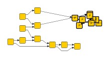
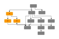
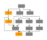
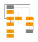
Effects of component assignment strategies shows the outcome of partial layout calculation using different assignment strategies to form the subgraph component(s) from a set of partial nodes.
- Core Layout
- coreLayout
- Determines the actual layout algorithm that is used for each single subgraph component.
The core layout algorithm can also be set at creation time:
// Setting the core layout algorithm right away.
const pl = new PartialLayout(new CircularLayout())
- Subgraph Component Placement
- subgraphPlacement
- Determines how to place each subgraph component after layout calculation.
Subgraph components are placed in a way that they do not overlap with each other
or with the fixed remainder of the diagram.
When Consider Node Alignment
is enabled, the resulting placement is further refined.
- BARYCENTER A subgraph component is placed as near as possible to its fixed neighbor nodes, respectively already placed other subgraph components. This yields short edges between the subgraph component and the fixed remainder of the diagram.
- FROM_SKETCH A subgraph component is placed as near as possible to its initial position. If space permits, this allows in-place re-arranging of subgraph components, for example.
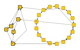
Different placement for subgraph components shows how a set of partial nodes (emphasized nodes to the left) is placed as a single subgraph component close to its original position, respectively close to its neighbors. The original circular layout of the diagram (the fixed elements) is left unaltered. Note that subgraph component is laid out using circular layout, too.
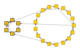
Using an identity core layout algorithm, i.e., an implementation that does not alter the positions of nodes or edges, partial layout can be used to find new optimal positions for entire subgraph components.
- Consider Node Alignment
- considerNodeAlignment
- Specifies whether or not nodes should be aligned. If set to true, the algorithm tries to center-align nodes from subgraph components with nodes from the fixed remainder of the graph.
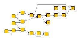
Partial layout with and without node alignment enabled is illustrated in Node alignment.
Basic Options
- Minimal Node Distance
- minimumNodeDistance
- Determines the minimal distance between subgraph components as well as between a subgraph component and any of its fixed neighbors.
- Maximal Duration
- maximumDuration
- Sets the preferred maximum duration of the layout process in milliseconds. By default, the algorithm runs without time restriction. Decreasing this value gives better control over the runtime at the cost of layout quality.
Edge Routing Options
The edge routing style that is used for routing partial edges as well as edges between different subgraph components (so-called inter-edges) can be specified using the edgeRoutingStrategy property. Available options are
- ORGANIC
- Each edge path will be routed as a straight line or a curved line. Uses class OrganicEdgeRouter.
- ORTHOGONAL
- Each edge path will be routed in an orthogonal style, i.e. only vertical and horizontal line segments will be used. Uses class EdgeRouter.
- OCTILINEAR
- Each edge path will be routed using octilinear routing style, i.e. line segments where the slope is a multiple of 45 degree will be used. Uses class EdgeRouter.
- STRAIGHTLINE
- Each edge path will be routed as a straight line connecting the start node and end node.
- AUTOMATIC
- Tries to determine whether the edge routing style in the fixed remainder of the graph is orthogonal or not. If so, edge paths will be routed orthogonally, otherwise straight-line.
Grouped Graphs
PartialLayout supports layout of partial elements in grouped graphs. Conceptually, though, if a group node belongs to the set of fixed elements, then any children that are partial nodes require the geometry of the group node to be spacious enough to accommodate the resulting layout of the subgraph components.
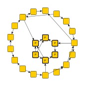
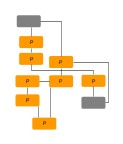
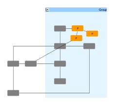
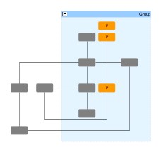
Support for partial layout within a group node shows the result of a partial layout within a group node that itself belongs to the set of fixed elements. In particular, this means that the group node’s geometry will not be altered, i.e., neither its size nor its position is allowed to change. The quality of a partial layout in such a situation depends to a great extent on the available space within the group node.
Node Alignment
An existing layout where some nodes lack proper alignment can be improved by marking
the nodes as partial, setting property Subgraph Component Assignment Strategy
to SINGLE,
and enabling Consider Node Alignment.
Layout Data
When using class PartialLayout, supplemental layout data for a graph’s elements can be specified either by using class PartialLayoutData or by registering data providers with the graph using given look-up keys. Supplemental layout data lists all properties of PartialLayoutData and the corresponding look-up keys that PartialLayout tests during the layout process in order to query supplemental data.
Providing supplemental layout data is described in detail in Layout Data.
Supplemental layout data
affectedNodes - For each node a boolean value indicating whether it is a so-called partial node or not. Note that the set of partial nodes also induces partial edges: an edge that is incident to a partial node is implicitly treated as a partial edge.Data Provider Key: AFFECTED_NODES_DP_KEYMaps from node to boolean
affectedEdges - For each edge a boolean value indicating whether it is a so-called partial edge or not. Note that an edge that is incident to a partial node is implicitly treated as a partial edge, too.Data Provider Key: AFFECTED_EDGES_DP_KEYMaps from edge to boolean
componentIds - For each node an arbitrary Object indicating the subgraph component it is affiliated with.Data Provider Key: COMPONENT_ID_DP_KEYMaps from node to Object
directedEdges - A collection of edges that are considered as directed by the layout.Data Provider Key: DIRECTED_EDGES_DP_KEYMaps from edge to ItemCollection<TItem>
nodeHalos - A NodeHalo object that specifies the halo sizes at each side of a node.Data Provider Key: NODE_HALO_DP_KEYMaps from node to NodeHalo
sourcePortConstraints - For each edge a PortConstraint object encoding its source end’s port constraint.Data Provider Key: SOURCE_PORT_CONSTRAINT_DP_KEYMaps from edge to PortConstraint
targetPortConstraints - For each edge a PortConstraint object encoding its target end’s port constraint.Data Provider Key: TARGET_PORT_CONSTRAINT_DP_KEYMaps from edge to PortConstraint
sourcePortCandidates - For each edge a ICollection<T> of PortCandidate objects that encode the subset of desired anchor locations where the source port likes to connect to.Data Provider Key: SOURCE_PORT_CANDIDATE_COLLECTION_DP_KEYMaps from edge to Collection
targetPortCandidates - For each edge a ICollection<T> of PortCandidate objects that encode the subset of desired anchor locations where the target port likes to connect to.Data Provider Key: TARGET_PORT_CANDIDATE_COLLECTION_DP_KEYMaps from edge to Collection
abortHandler - An AbortHandler instance that will be queried by the layout algorithm to determine whether layout calculation shall be terminated.Data Provider Key: ABORT_HANDLER_DP_KEYMaps from graph to AbortHandler
partitionGridData - Specifies a PartitionGrid for the partial layout.
PartitionGridData.grid - Specifies the partition grid structure for the graph. Can also be defined using the rowIndices and columnIndices properties.Data Provider Key: PARTITION_GRID_DP_KEYMaps from graph to PartitionGrid
PartitionGridData.cellIds - Specifies the partition cell id for a node. Alternatively, cell indices for a node can be specified using the rowIndices and columnIndices properties.Data Provider Key: PARTITION_CELL_ID_DP_KEYMaps from node to PartitionCellId