Radial Layout
Class RadialLayout is a layout algorithm that arranges the nodes of a graph on concentric circles.
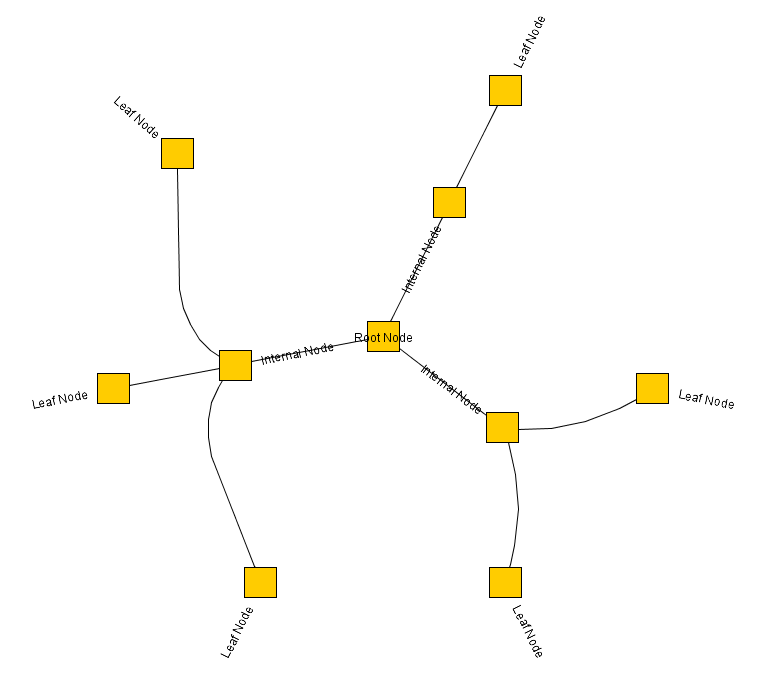
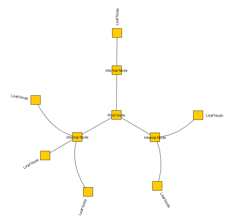
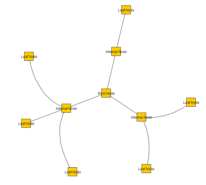
The layout calculation begins by conceptually reducing the graph to a tree structure. The root node of this tree is considered the center of all circles. Each child node in the tree is then placed on the next outer circle, within the sector of the circle that its parent node reserved. After placing the nodes in a tree structure, all edges that were initially ignored are re-established. The radii of the circles are then calculated, taking into account the sector sizes required by each subtree.
This layout style is well-suited for visualizing directed graphs and tree-like structures.
Terminology
The circles are also referred to as layers. The layer index increases from the center outwards.

Relevant Classes
The following table lists the relevant classes and interfaces for the radial layout algorithm in yFiles for HTML.
| Classname | Description |
|---|---|
Main algorithm class. |
|
Layout data class to provide additional item-specific options. This can be created using the factory method createLayoutData |
Basic Options
Center Nodes
The policy for choosing the center node from the graph’s node set can be determined by using the centerNodesPolicy property. The following policies are available:
- DIRECTED
-
Chooses the center node from the set of nodes that have no predecessors. If this set is empty, an arbitrary node of the graph is chosen as the center node.
- CENTRALITY
-
The node with the highest centrality is chosen as the center node.
- WEIGHTED_CENTRALITY
-
The node with the highest weighted centrality is chosen as the center node. This is the default setting.
In addition, you can specify custom center nodes using the centerNodes layout data property. In this case, the layout automatically uses those center nodes and ignores the centerNodesPolicy property.
If more than one node is marked as a center node, all center nodes are placed on the innermost circle, and the actual center position remains empty.
Layering Strategy
The layeringStrategy property determines how nodes are distributed across the layers. The following strategies are available:
- BFS
-
Layering based on a breadth-first search (BFS) algorithm. All edges will span a maximum of one layer in the resulting drawing. Edges between nodes on the same layer are possible. This is the default strategy.
- HIERARCHICAL
-
The layer distance of an edge is the absolute difference between the layer numbers of its source and target node. Layer assignment will minimize the total sum of layer distances for all edges in the layout.
- DENDROGRAM
-
This layering strategy creates a dendrogram drawing. Nodes are placed on the outermost circle possible without crossing their successors. In tree graphs, leaves are placed on the outermost circle, and their parents are placed further inward. For general graphs, the outermost circle contains nodes without successors in their sector.
The distance between layers depends on the space required by the subtrees. However, you can control the layer spacing and define a minimum distance.
Layer Spacing
- layerSpacing
-
Defines a unit value for the distance between circles. Each circle’s radius is a multiple of this value.
Minimal Layer Distance
- minimumLayerDistance
-
Defines the minimum distance between layers.
Edge Routing
Edge routing options include different routing policies that can be specified using the edgeRoutingStyle property:
- POLYLINE
-
Polyline edge routing. Edges will be routed with straight lines, if possible, or have bends on the circles.
- ARC
-
Arc edge routing. The source and target of an edge, as well as one bend on each spanned circle, are used as main control points. Additional control points are inserted in-between to create an arc-like edge. This is the default setting.
- RADIAL_POLYLINE
-
Radial polyline routing. Edges will be routed as a series of straight and arc segments. At the angle of the source and the target node, the edge will go straight from the center, and when the angle changes, the edge follows the circles.
- CURVED
-
Curved edge routing. Edges will be routed as curved Bezier paths.
Note that, regardless of the edge routing policy, overlaps of edge paths with nodes cannot always be prevented. In particular, this affects edges that span multiple circles (i.e., layers).
Labeling
Besides the generic labeling support as described in Generic Labeling, which is available with all yFiles layout algorithms, RadialLayout also features integrated node labeling.
Node labels can be taken into consideration when determining the positions for the nodes of the graph. With this strategy, it is guaranteed that no label will overlap other objects in the diagram. Integrated labeling can be enabled using the following property:
- nodeLabelPlacement
-
Determines the labeling strategy for node labels.
Enabling the integrated node labeling support of class RadialLayout means that each node label will be placed and arranged so that there are no overlaps of node labels with each other or with graph elements (other than their respective node).
RadialLayout supports the following integrated node labeling policies:
- HORIZONTAL
-
Each node label will be placed at the center of its node, with horizontal orientation. Multiple node labels will be placed center-aligned and stacked.
- RAY_LIKE
-
Node labels of all nodes, except the root node, will be oriented ray-like, i.e., with the same angle as the node. Additionally, the node labels of nodes without successors within their sector will be placed outside their node and in the available space between their circle and the next circle. The node labels of all other nodes will be placed in the available space between their circle and the previous one. Multiple, ray-like oriented node labels will be left-aligned. The node labels of the root node will be placed at the center of their node, with horizontal orientation. Also, node labels that do not use a "free" label model will be placed this way. See also below. This is the default setting.
- RAY_LIKE_LEAVES
-
The node labels of nodes without successors within their sector will be oriented ray-like, i.e., with the same angle as the node. Additionally, these node labels will be placed outside their node and in the available space between their circle and the next circle. Other node labels will be placed at the center of their node, with horizontal orientation. Also, node labels that do not use a "free" label model will be placed this way. See also below.
Note that ray-like oriented node labels are only supported by integrated labeling for node labels that use a "free" label model, e.g., FreeNodeLabelModel. Furthermore, instead of using the integrated node labeling, property nodeLabelPlacement allows to specify that the algorithm considers the current position of the labels without producing overlaps (value CONSIDER).
Node Margins
RadialLayout supports node margins by default if they are declared using the layout data’s nodeMargins property. The layout considers any specified additional padding around nodes; however, edges can cross through these areas in the resulting diagram.
Edge Bundling
RadialLayout supports Edge Bundling for the non-tree edges in a diagram, bundling their paths to follow similar routes.
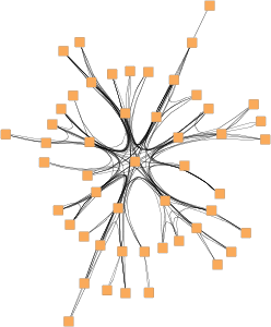
The EdgeBundling class handles the setup and configuration of edge bundling. RadialLayout provides the following property to access its instance of this class:
- edgeBundling
-
Property to access the EdgeBundling instance to configure edge bundling-related drawing options.