Port Placement
The points where an edge connects to its source and target nodes are called ports. In some applications, ports are important and have a fixed position, sometimes even with a visual representation. In other applications, they can be ignored. Similarly, some layout algorithms distribute the ports to best fit their criteria, while other algorithms place them in the middle of the node.

|
Note
|
Internally, the layout algorithms are not aware of ports. They may place the start and end points of edges, though. Further, these locations might be restricted, or some rules can be defined to restrict them. |
This section describes how to control the port placement of automatic layout algorithms. Note that the layout executor can apply many rules with simple settings.
Automatic Port Handling by LayoutExecutor
While ports are part of the data model in the view part, layout algorithms generally do not handle them automatically. However, LayoutExecutor provides settings that make layout algorithms aware of the ports.
Keeping the Port Location
Setting portPlacementPolicies to KEEP_PARAMETER for an IPort keeps the location of the port fixed relative to the node layout. This is useful when ports are already placed in a specific location on the nodes and you want to prevent them from being altered by the layout algorithm. Internally, when this mode is enabled, the LayoutExecutor automatically creates fixed port candidates at the port’s current location.
|
Important
|
This setting is ignored if port candidates are explicitly registered. |
|
Note
|
Not all layout algorithms natively support port candidates. These algorithms typically include a PortPlacementStage in their layout stages, which handles port candidates as a post-processing step. |
This feature is disabled by default.


Grouping Edges that Connect to the Same Port
A single port can be the source or target of multiple edges. However, layout algorithms are typically not aware of ports and might place the edge end points at different locations.
The LayoutExecutor automatically groups edges that connect to the same port. To disable this behavior, define custom port groups that place each edge end point in its own port group.
|
Important
|
Ports are not grouped automatically if port groups are already defined through layout data. |


Placing Ports on the Node’s Outline
Layout algorithms treat nodes as rectangular objects, using the bounds defined by their layout. Therefore, the algorithms typically place ports either at the border or the center of a node’s rectangular bounds. However, nodes can be visualized with more complex shapes than simple rectangles. Setting the portAdjustmentPolicies property enables the LayoutExecutor to place ports on the outline of a node. The connecting edge’s first or last segment will be prolonged or shortened to connect to that port.
|
Important
|
This setting is ignored if fixed port candidates are defined. This is especially true if the port location should remain unchanged (see Keeping the Port Location). |
By default, edges are lengthened if their port is outside the node’s outline (i.e., the port adjustment policy is set to LENGTHEN).


Placing Port Labels
Since layout algorithms are not aware of ports, the automatic label placement is also not aware of port labels. However, ports are bound to nodes and the end points of edges, therefore their labels can be treated as node labels or edge labels. LayoutExecutor automatically handles this conversion. Since the best way to handle port labels might vary, the policy can be set per port using the portLabelPolicies property.
Restricting Port Locations
To restrict the locations where an edge connects to its source or target node during automatic layout, yFiles for HTML provides the concept of port candidates. This concept is implemented by the LayoutPortCandidate class.
Port candidates can be used with both nodes and edges. LayoutPortCandidates are usually not created directly, but instead via NodePortCandidates or EdgePortCandidates.
The layout algorithms provided by yFiles for HTML vary in the degree to which they consider port candidates. The major layout algorithms that support port candidates directly are listed in section Layout Algorithms Supporting Port Candidates.
Port Candidates for Nodes
When used with nodes, port candidates provide a way to:
-
Restrict anchor locations on nodes. You can specify either exact anchor locations on a node (called fixed port candidates) or restrict the anchor to any location on a specific side of a node (called free port candidates).
-
Associate costs with a given anchor location. This establishes a priority among a given set of anchor locations. Anchor locations with a low cost are preferred over anchor locations with higher costs.
-
Limit the number of connecting edges at a given anchor location, called the capacity of the port candidate.
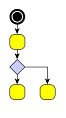
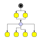
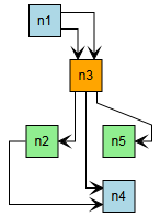
A typical example for the use of port candidates is a flow diagram as shown in Using port candidates to control connection points: The diamond shape, which visualizes a switch, should have its incoming edge connecting at the top. The first outgoing edge should connect at the bottom (first image), the second at the right, and the third at the left (second image). If there are more outgoing edges, these should connect at the bottom. Similarly, if there is more than one incoming edge, these should connect at the top (third image).
The collection of port candidates at a node is defined by an instance of the NodePortCandidates class. This class offers methods to create and add port candidates with specified properties to the set. These include the capacity, which specifies the allowed number of connecting edges at that side or anchor location.
Matching Edges with Port Candidates at Nodes
|
Note
|
The description in this section assumes the basic case where port candidates are only defined at nodes. For the case where there are port candidates at both nodes and edges, see section Matching Port Candidates at Nodes and at Edges. |
Matching port candidates is the process of assigning a node’s edges to the available port candidates. If a node is associated with a collection of port candidates via a NodePortCandidates object, all edges connecting to that node are distributed among the available port candidates with respect to:
-
the costs of a given port candidate
-
the number of edges that are allowed to connect to a given port candidate
For example, when the limit of allowed edges for a given port candidate with costs k is reached, i.e., the given port candidate is said to be saturated, then the next least expensive port candidate among the remaining ones is chosen to connect edges to.
Defining NodePortCandidates demonstrates how to create node port candidates for the diamond node shown in Using port candidates to control connection points. First, port candidates for the four corners of the diamond are defined. The number of connecting edges for these candidates is limited to 1. To ensure that the edges first connect to the corners before the additional candidates are occupied, a higher cost is associated with these latter candidates.
const layout = new HierarchicalLayout()
const data = layout.createLayoutData(graph)

const candidates = new NodePortCandidates()

// the node has the size (30, 30) with the point (0, 0) at the center
// so the coordinates for the top corner are (0, -15)

// create a candidate at the top corner with cost 0 and capacity 1
candidates.addFixedCandidate(PortSides.TOP, new Point(0, -15), 0, 1)
// do the same for the other three corners
candidates.addFixedCandidate(PortSides.BOTTOM, new Point(0, 15), 0, 1)
candidates.addFixedCandidate(PortSides.RIGHT, new Point(15, 0), 0, 1)
candidates.addFixedCandidate(PortSides.LEFT, new Point(-15, 0), 0, 1)

// to allow more edges to connect at the top and bottom
// create extra candidates and allow Number.MAX_VALUE edges to connect

// to avoid that these candidates are occupied before the others
// associate a cost of 1 with them
candidates.addFixedCandidate(
  PortSides.TOP,
  new Point(0, -15),
  1,
  Number.MAX_VALUE
)
candidates.addFixedCandidate(
  PortSides.BOTTOM,
  new Point(0, 15),
  1,
  Number.MAX_VALUE
)

// associate the node with the candidates
data.ports.nodePortCandidates.mapper.set(node, candidates)To influence the matching process, port candidates can additionally be associated with the edges. This permits fine-grained control of the matching process. See section Matching Port Candidates at Nodes and at Edges for more details.
Port Candidates for Edges
Similar to nodes, port candidates, when used with edges, provide a way to:
-
Restrict anchor locations at the source or target node of an edge. You can specify either exact anchor locations at a node (called fixed port candidate) or restrict the anchor to any location on a specific side of a node (called free port candidate).
-
Associate costs with a given anchor location. This establishes an order of precedence among a given set of anchor locations. Anchor locations with a low cost are favored over anchor locations with higher costs.
The collection of port candidates at the source or target of an edge is defined by an instance of the EdgePortCandidates class. This class offers methods to create and add port candidates with specified properties to the set. Unlike node port candidates, there is no point in specifying the number of edges at an anchor location since edge port candidates are defined per single edge.
const layout = new HierarchicalLayout()
const data = layout.createLayoutData(graph)

// blue edges should start near the right upper corner and end near the left upper corner
const blueSourceCands = new EdgePortCandidates().addFixedCandidate(
  PortSides.RIGHT,
  new Point(15, -10)
)
const blueTargetCands = new EdgePortCandidates().addFixedCandidate(
  PortSides.LEFT,
  new Point(-15, -10)
)

// green edges should start near the right lower corner and end near the left lower corner
const greenSourceCands = new EdgePortCandidates().addFixedCandidate(
  PortSides.RIGHT,
  new Point(15, 10)
)
const greenTargetCands = new EdgePortCandidates().addFixedCandidate(
  PortSides.LEFT,
  new Point(-15, 10)
)

// use LayoutData to apply the source and target port candidates
data.ports.sourcePortCandidates.mapperFunction = (edge: IEdge) =>
  edge.tag === 'blue'
    ? blueSourceCands
    : edge.tag === 'green'
      ? greenSourceCands
      : null

data.ports.targetPortCandidates.mapperFunction = (edge: IEdge) =>
  edge.tag === 'blue'
    ? blueTargetCands
    : edge.tag === 'green'
      ? greenTargetCands
      : null

// and perform a layout
graph.applyLayout(layout, data)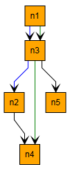

const layout = new HierarchicalLayout()
const data = layout.createLayoutData(graph)

data.ports.sourcePortCandidates.mapperFunction = (edge: IEdge) =>
  edge.sourceNode.tag === 'blue'
    ? new EdgePortCandidates().addFreeCandidate(PortSides.RIGHT)
    : edge.sourceNode.tag === 'green'
      ? new EdgePortCandidates().addFreeCandidate(PortSides.LEFT)
      : null

data.ports.targetPortCandidates.mapperFunction = (edge: IEdge) =>
  edge.sourceNode.tag === 'blue'
    ? new EdgePortCandidates().addFreeCandidate(PortSides.RIGHT)
    : edge.sourceNode.tag === 'green'
      ? new EdgePortCandidates().addFreeCandidate(PortSides.RIGHT)
      : null

// and perform a layout
graph.applyLayout(layout, data)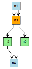
The Logic Gates demo application shows in detail how to use port candidates with the HierarchicalLayout.
Note that fixed port candidates at edges may be created without explicitly defining the port location. In this case, the current port position will be used. This feature exists mostly for backwards compatibility, and it is usually clearer to set the port location explicitly.
Matching Port Candidates at Nodes and at Edges
If port candidates are defined both at the nodes and the edges, the layout algorithms attempt to match them. A port candidate at a node may only be used by an edge if one of the port candidates associated with the edge’s end point matches. For more precise control over which candidates may match, each port candidate can be assigned a matching ID.
Port candidates match if:
-
their matching IDs are the same, or at least one matching ID is
null, -
they belong to a common side, or at least one side is ANY, and
-
if both port candidates are fixed, they describe the same position.
|
Note
|
The matching is always between port candidates of an edge (i.e., EdgePortCandidates) and port candidates of the associated source or target node (i.e., NodePortCandidates). If two edges should share the same port, use Edge and Port Grouping instead. |
Creating matching port candidates illustrates how matching IDs may be used to simulate different kinds of ports, where edges may only use some of the ports.
const layout = new HierarchicalLayout()
const data = layout.createLayoutData(graph)

// all nodes should provide two fixed ports at the top and bottom side;
// the available ports are subdivided into "red" and "blue" ports
data.ports.nodePortCandidates.constant = new NodePortCandidates()
  .addFixedCandidate({
    side: PortSides.TOP,
    offset: new Point(-5, -15),
    matchingId: 'red'
  })
  .addFixedCandidate({
    side: PortSides.TOP,
    offset: new Point(5, -15),
    matchingId: 'blue'
  })
  .addFixedCandidate({
    side: PortSides.BOTTOM,
    offset: new Point(-5, 15),
    matchingId: 'red'
  })
  .addFixedCandidate({
    side: PortSides.BOTTOM,
    offset: new Point(5, 15),
    matchingId: 'blue'
  })

const spcMapper = data.ports.sourcePortCandidates.mapper
const tpcMapper = data.ports.targetPortCandidates.mapper

// the source port of edge e1 can be any "red" port provided by the source node on its top side
spcMapper.set(
  e1,
  new EdgePortCandidates().addFreeCandidate({
    side: PortSides.TOP,
    matchingId: 'red'
  })
)

// the target port of edge e1 can be any port provided by the target node (matches each matchingId)
tpcMapper.set(
  e1,
  new EdgePortCandidates().addFreeCandidate({ side: PortSides.ANY })
)

// the source port of edge e2 can be any "blue" port provided by the source node
spcMapper.set(
  e2,
  new EdgePortCandidates().addFreeCandidate({
    side: PortSides.ANY,
    matchingId: 'blue'
  })
)

// the target port of edge e2 can be any port provided by the target node on its bottom side
tpcMapper.set(
  e2,
  new EdgePortCandidates().addFreeCandidate({ side: PortSides.BOTTOM })
)Layout Algorithms Supporting Port Candidates
Only some layout algorithms directly support port candidates as part of their core layout process. Layout support for port candidates lists these layout algorithms and routers.
| Layout Style | Class Name | Note |
|---|---|---|
Hierarchical |
HierarchicalLayout obeys port candidates by default as soon as they are set. See the description of the hierarchical layout style for more information. |
|
Partial |
Both PartialLayout and ClearAreaLayout obey port candidates for re-routed edges. |
|
Tree |
Nearly all predefined subtree placer implementations that can be used with the tree layout algorithm obey port candidates by default as soon as they are set. See the description of the tree layout for more information. |
|
Orthogonal / Polyline Edge Routing |
The EdgeRouter obeys port candidates as soon as they are set. See the descriptions of EdgeRouter for more information. |
|
Straight Line Edge Routing |
The StraightLineEdgeRouter obeys port candidates as soon as they are set. |
A special case is RecursiveGroupLayout since it delegates to other layout algorithms. Therefore, RecursiveGroupLayout supports port candidates if the applied layout algorithms do.
Restricting Ports for Layout Algorithms that Do Not Support Port Candidates
Some layout algorithms do not directly support port candidates. In these cases, they typically include the PortPlacementStage in their layout stages (see Layout Stages for more details on the layout stage concept). This stage ensures that the port candidates are obeyed in a post-processing step.
Technically, this stage moves ports after the actual layout algorithm has finished. This might result in unexpected edge paths, especially if the original edge paths were orthogonal. In such cases, setting routeCorrectionPolicy to LOCAL_ORTHOGONAL might be helpful. With this setting enabled, the edges are routed orthogonally within the area around the node to reach their new ports. However, for straight edge paths, setting routeCorrectionPolicy to MOVE_PORTS or MOVE_PORTS_TO_BORDER (the default) is preferable.
|
Note
|
The optimal setting for routeCorrectionPolicy depends on the layout algorithm. Generally, algorithms that produce straight edges (like organic layout) should be used with MOVE_PORTS or MOVE_PORTS_TO_BORDER. |