Circular Layout
Class CircularLayout is a layout algorithm that visualizes interconnected ring and star topologies. It is well-suited for applications in:
-
Social networking (criminology, economics, etc.)
-
Network management
-
WWW visualization
-
eCommerce
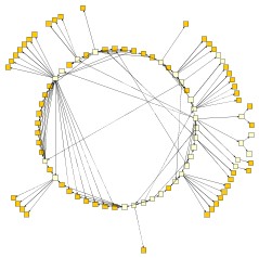
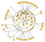
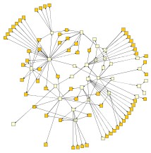
CircularLayout produces layouts that emphasize group and tree structures within a network. It creates node partitions by analyzing the network’s connectivity structure and arranges the partitions as separate circles. The circles are then arranged in a radial tree layout.
Basic Options
Class CircularLayout provides a set of options that affect its layout behavior. These options can be set using the properties of class CircularLayout. The options are documented within the API documentation of class CircularLayout.
Additionally, the properties partitionDescriptor and backboneLayout allow configuring the layout delegates. These layout algorithms arrange the circle and tree components of the diagram, respectively. Modifying these options also affects the overall layout behavior of CircularLayout.
The property partitioningPolicy controls which policy is used to partition the nodes of the graph. Each node partition will be arranged either on a separate circle or as a separate disk (see also node partition layout style below). Available options are:
- BCC_COMPACT
-
Each partition represents a biconnected component of the graph. A biconnected component consists of nodes that are reachable by two node-disjoint paths. In other words, removing a single node does not split the component into two components. Nodes that belong to more than one biconnected component will be assigned exclusively to one partition.
- BCC_ISOLATED
-
Node partitions will be formed as with BCC_COMPACT, with the difference that all nodes belonging to more than one biconnected component will be assigned an isolated partition.
- SINGLE_CYCLE
-
All nodes will be assigned to the same partition; that is, they will be arranged on a single circle.
If the predefined policies do not suit specific needs, custom partitions can be defined using the layout data property partitions. The figure Effect of option Layout Style shows the effect of different partition policies applied to CircularLayout.
- fromSketchMode
-
If enabled, the layout algorithm interprets the initial graph layout as a sketch for the desired outcome of the layout process. The algorithm tries to identify the nodes that should lie on a node partition’s circle or disk boundary and maintain their cyclic order around the center of the node partition. (See also Partition Arrangement Options below.) Additionally, when layout style BCC_COMPACT is used, the layout algorithm also tries to maintain the cyclic order of entire node partitions that connect to a common node.
Partition Arrangement Options
CircularLayout offers different arrangement styles for the node partitions of a graph. These styles are configured using an instance of PartitionDescriptor, accessible through the property partitionDescriptor. The nodes from a partition can be arranged either as a circle or using one of the available disk layouts. You can specify the arrangement using the style property:
- CYCLE
-
All nodes from a given partition are placed on a circle.
- DISK
-
The nodes from a given partition that connect to nodes from other partitions are placed on the disk’s boundary. All other nodes are placed inside the disk.
- ORGANIC
-
The organic layout paradigm arranges the nodes from a partition within a disk. Nodes that connect to nodes from other partitions can be placed either inside or on the boundary of the disk.
- COMPACT_DISK
-
The nodes of the given partition are densely packed on the disk. This style is most suitable for partitions with few edges. It is recommended to enable external edge routing.
All three disk arrangement styles result in graph layouts that are smaller, i.e., consume less space, than the circle arrangement style. The figure Node partition layout styles presents the available node partition layout styles and their effects for a given graph.
The size and compactness of the circles/disks can be controlled by the property partitionDescriptor as follows.
- minimumNodeDistance
-
Determines the minimum distance between the borders of two adjacent nodes on the circle or the disk’s boundary. The smaller the distance, the more compact the resulting layout.
- automaticRadius
-
Specifies whether to determine the radius of each circle/disk in the layout automatically. An automatically chosen radius is usually the smallest possible radius that obeys minimumNodeDistance.
- fixedRadius
-
If automaticRadius is not set, then this option determines the fixed radius for all circles/disks in the resulting layout. minimumNodeDistance will be ignored in this case.
Edge Routing Policy
By default, edges are routed as simple straight lines (interior routing). Edges that connect nodes within the same circle (i.e., partition) can optionally be routed around the exterior of the circle in an arc-like fashion.
This can improve the readability of layouts with single cycles by reducing the number of edge crossings inside the circle. Therefore, this option is most suitable when you have partitions or single cycles where the nodes are highly connected.
The property edgeRoutingPolicy controls the routing policy, determining which edges are routed internally and which are routed externally.
- INTERIOR
-
All edges are routed internally as straight lines (default behavior).
- EXTERIOR
-
Edges connecting nodes of the same partition are routed around the exterior of the circle. Only edges that connect direct neighbors are routed as straight lines.
- AUTOMATIC
-
The set of edges that are routed externally is chosen automatically. The heuristic selection aims to reduce the number of edge crossings on the interior of the circle and avoids creating edge crossings between exterior edges.


Exterior Edges - Settings
You can further configure the exterior edges that are routed around the circle using the CircularLayoutExteriorEdgeDescriptor class. This class is accessible through the exteriorEdgeDescriptor property. It offers various properties, such as the distance between adjacent exterior edges. See the API documentation for details.
Tree Arrangement Options
The options for the internally used backboneLayout influence the compactness of the tree-like components that this layout algorithm produces. The tree-like structures are the parts of the layout that are not part of the circularly arranged node groups.
- preferredChildSectorAngle
-
This setting determines the angular range of the sector that will be reserved for the children of a root node. The possible angular range lies between 1 and 359 degrees. The remaining angular range (360 minus x) will be automatically used to accommodate the edge that connects to the root node. The smaller the chosen value, the greater the impression that the nodes drive away from their root nodes and the center of the graph. Generally speaking, the compactness of the layout will decrease with smaller values. Very small values will lead to layouts that consume a lot of space.
- minimumEdgeLength
-
Determines the minimum length of an edge that connects two nodes that lie on separate circles (tree edges). The smaller the chosen value, the more compact the resulting layout.
- compactnessFactor
-
This parameter influences the length of the tree edges as it is computed by the layout algorithm. The larger the compactness factor, the shorter the tree edges and the more compact the overall layout.
- allowOverlaps
-
If activated, this option further increases the compactness of the resulting layout, but potentially introduces slight node overlaps.
The following tree arrangement options, which also influence the compactness, are set directly on the CircularLayout.
- maximumDeviationAngle
-
Whenever tree edges connect to a node that lies on a circle together with other nodes, the layout algorithm tries to direct that edge in such a way that its prolongation crosses through the center of the circle. This is not always possible, though, for example, if more than one tree edge connects to the same circle node. This parameter determines the allowed angular deviation from the optimal edge direction as described above. The bigger the chosen value, the more compact the resulting layout. If a value smaller than 90 degrees is chosen, then the tree-edges might cross through the circularly arranged components.
- placeChildrenOnCommonRadius
-
Enables tighter drawings by using adapted radii for child nodes. By default, the nodes in tree-like structures connecting to a circle are always placed on a common radius according to their distance from the root node. Tighter drawings can be achieved by abandoning the common radius and instead placing these child nodes using radii adapted to the size of an actual child node and the sizes of nodes in its vicinity.
Child node placement in tree structures shows a circular layout using the default setting and the result of using adapted radii for the nodes in tree-like structures connecting to a circle. Note that the circle(s) themselves are left unaltered.


Labeling
Edge labels can be placed automatically using the generic labeling support as described in Generic Labeling. The placement of edge labels can be enabled by setting edgeLabelPlacement to GENERIC.
CircularLayout supports different node labeling policies that can be configured using the nodeLabelPlacement property. The following options are available:
- IGNORE
-
Node labels will be ignored during the layout calculation. This setting ensures that node labels have no influence on the arrangement of nodes and edges in the layout.
- CONSIDER
-
Node labels will be considered during the layout calculation. The algorithm adjusts the positions of nodes and edges to avoid label overlaps and improve label visibility.
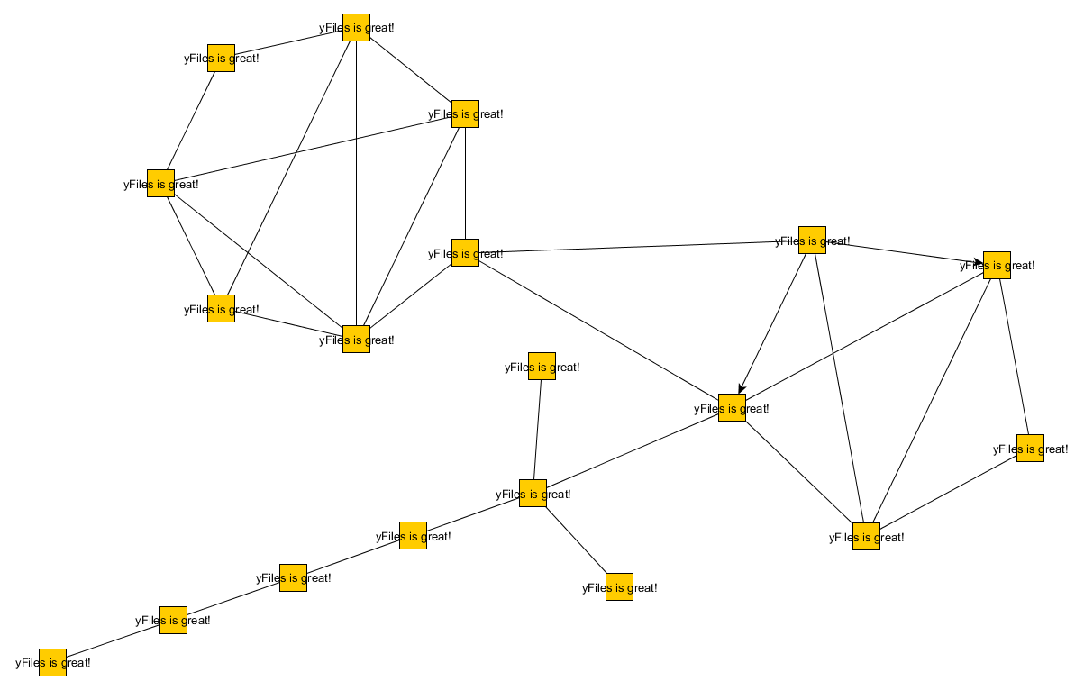
- HORIZONTAL
-
Each node label will be placed at the center of its node, with horizontal orientation. Multiple node labels will be placed center aligned and stacked. See also the figure below.
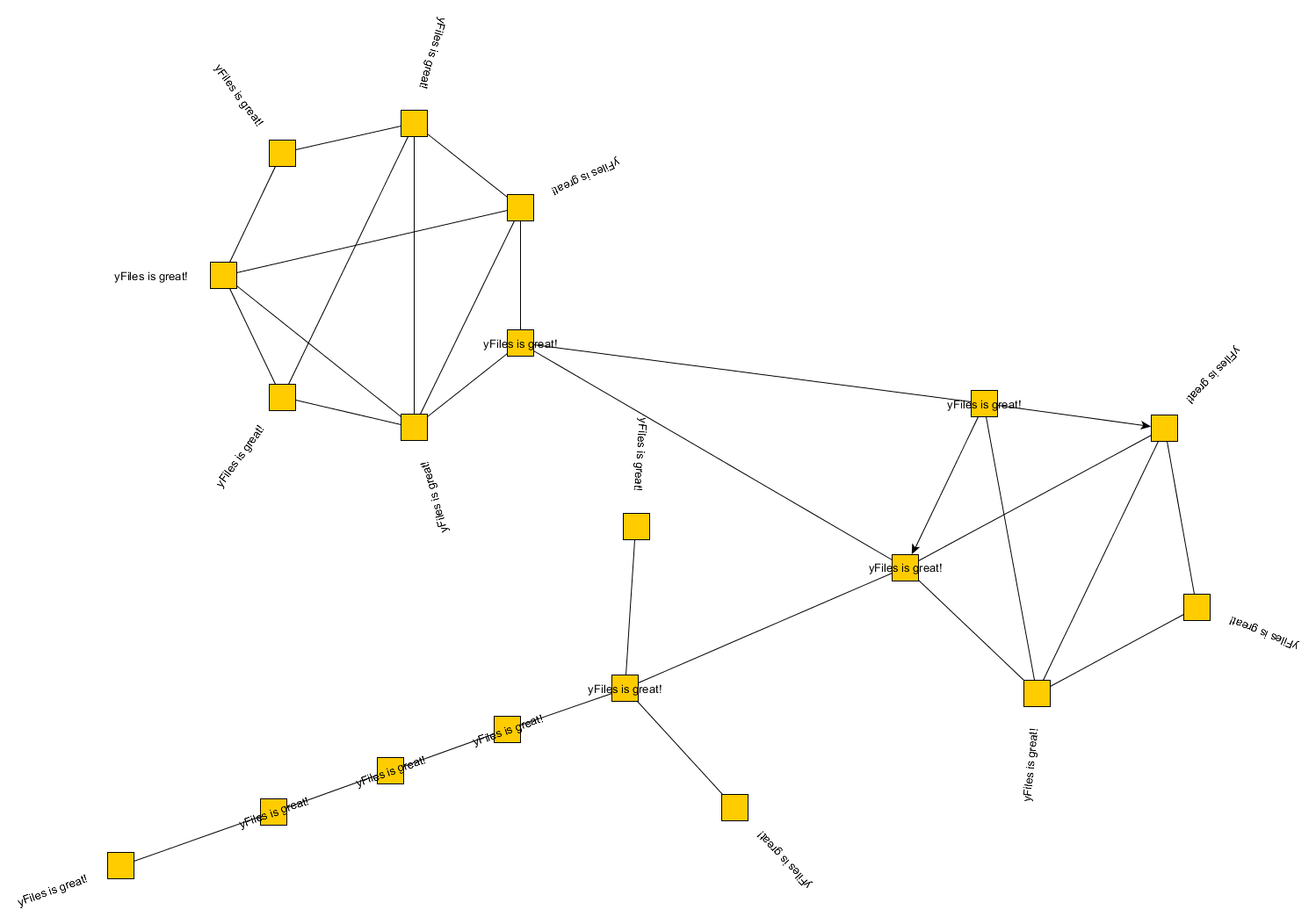
- RAY_LIKE
-
The algorithm places the label of nodes that belong to the perimeter of a circle ray-like outside the node with the same orientation as their nodes' incoming edge. If the partition style is BCC_COMPACT or BCC_ISOLATED, the labels of the nodes that are connected to more than one circular components will be also placed horizontal, even if they are placed on the perimeter of the circle. Labels of nodes that belong to a chain will be placed ray-like but inside the node with the same orientation as their nodes' incoming edge. See also the figure below.
- RAY_LIKE_LEAVES
-
The algorithm places the label of nodes with no children or of nodes that belong to the perimeter of a circle and have neighbors at the same circle ray-like outside the node with the same orientation as their nodes' incoming edge. The labels of the other nodes will be oriented horizontally and placed at the center of the corresponding node. This is the default setting. See also the figure below.
- GENERIC
-
The node labels are placed automatically using the generic labeling support as described in Generic Labeling.
Note that ray-like oriented node labels are only supported by integrated labeling for node labels that use a "free" label model, e.g., FreeNodeLabelModel.

Node Margins
CircularLayout supports node margins, which can be declared using nodeMargins. The layout considers any additional margins specified around nodes. However, because the edges are routed with straight lines, they may cross through these margin areas in the resulting diagram. Additionally, node margins might overlap if the internally used RadialTreeLayout allows nodes to overlap.
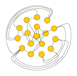
Edge Bundling
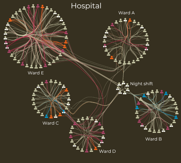
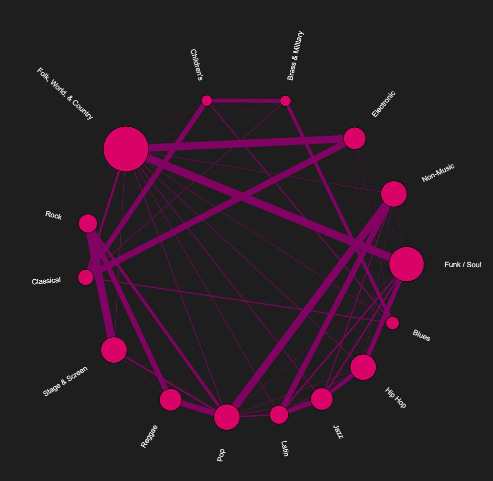
CircularLayout supports edge bundling, a feature that bundles the paths of edges in a diagram into cluster-like structures, so they follow similar routes.
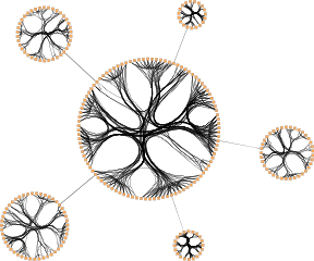
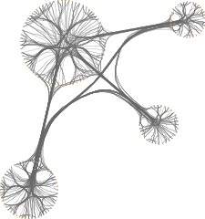
To perform edge bundling, a clustering algorithm identifies possible "community structures"—densely connected sets of nodes—within the graph. The paths of edges connected to nodes within the same cluster are then bundled together.
Edge bundling significantly reduces visual clutter in drawings of large graphs with many edges. Additionally, it highlights high-level patterns of edge routes and relationships between different groups of nodes, making them easier to recognize. Edge bundling is commonly used in bioinformatics, social network analysis, telecommunications, and fraud detection.
Edge bundling in CircularLayout is supported:
-
when the style is set to arrange as a circle
-
and the partitioningPolicy is set to one of BCC_COMPACT, SINGLE_CYCLE, or if custom partitions are defined via the layout data property partitions.
The actual setup and edge bundling configuration is handled by the EdgeBundling class. CircularLayout provides the following property to access its instance of this class:
- edgeBundling
-
Property to access the EdgeBundling instance to configure edge bundling-related drawing options.
This EdgeBundling instance holds an instance of class EdgeBundleDescriptor to store and retrieve default edge bundling values for all edges. The following property retrieves this default EdgeBundleDescriptor instance:
- defaultBundleDescriptor
-
Property to access the default edge bundling descriptor held by EdgeBundling.
In addition to the instance held by EdgeBundling, edge bundling descriptors can also be associated with individual edges to specify custom settings for them. Individual descriptors for edges are set through edgeBundleDescriptors.
Classes EdgeBundling and EdgeBundleDescriptor provide the means to configure drawing options related to edge bundling support in CircularLayout. Class EdgeBundling defines global settings for edge bundling, such as the bundling strength and quality. It also holds a default EdgeBundleDescriptor instance with fallback settings for the edges of a graph. Class EdgeBundleDescriptor configures the bundling settings of an individual edge, specifying whether:
-
an edge should be bundled
-
the direction of an edge should be considered
-
an edge should be approximated by a cubic Bezier curve
To configure global edge bundling settings, class EdgeBundling provides the following properties:
- bundlingStrength
-
Determines the tightness of the edge bundles. It accepts values from the interval [0.0, 1.0], where 0.0 corresponds to straight-line, non-bundled edges, and 1.0 corresponds to strongly bundled edges. For good readability with clearly visible bundles, a bundling strength greater than 0.8 is recommended.
- bundlingQuality
-
Determines the quality of the edge bundling. Higher values require more sophisticated methods to calculate the bundles, which can significantly increase the running time. This setting accepts values from the interval [0.0, 1.0]. For large graphs, values smaller than 0.2 are recommended.
The per-edge settings can be configured via the following properties in class EdgeBundleDescriptor:
- bundled
-
Determines whether an edge should be bundled.
- considerDirection
-
Determines if the direction of an edge should be considered. If enabled, incoming and outgoing edges connected to a node are bundled separately.
- bezierFitting
-
Determines whether the path of an edge should be approximated by a cubic Bezier curve. The approximation can significantly reduce the number of bends.
An EdgeBundleDescriptor instance can be specified individually for single edges using edgeBundleDescriptors. If an individual descriptor is not specified for an edge, the default EdgeBundleDescriptor instance registered with EdgeBundling will be used.
Optimizing Compactness
Several options influence the compactness of the circular layout. To optimize for compactness, consider the following:
-
Choose DISK or ORGANIC as style
-
Increase compactnessFactor
-
Set allowOverlaps to
true. Note that this might introduce node overlaps. -
Reduce minimumEdgeLength
-
Reduce minimumNodeDistance
-
Increase maximumDeviationAngle
-
Disable placeChildrenOnCommonRadius
-
Remove any nodeMargins
Increasing layout compactness shows the cumulative effect on layout compactness when changing the settings of the layout algorithm.
Returning Circle Indices
As an option, CircularLayout can write integer values for every node to circleIdsResult, representing the circle indices after layout calculation.
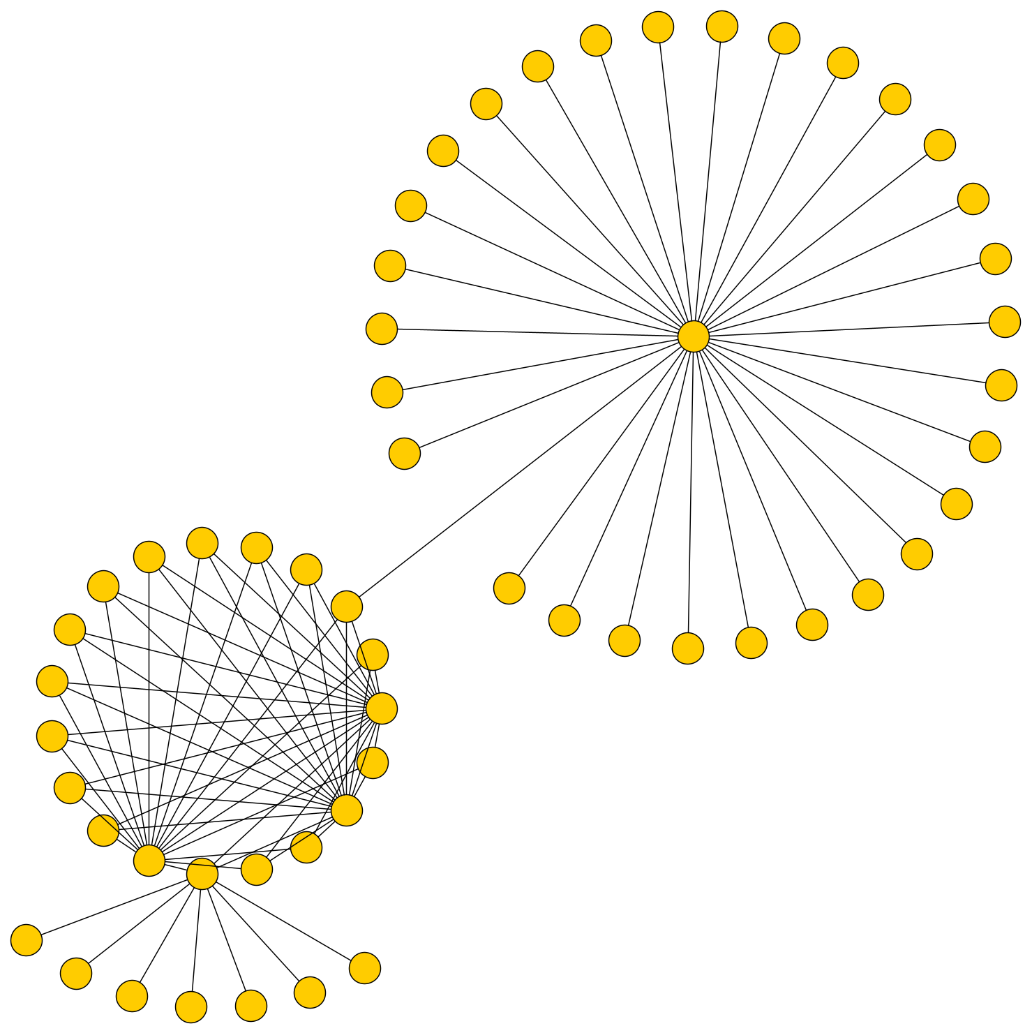
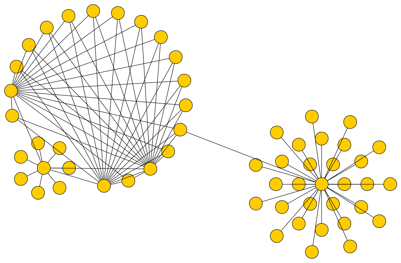
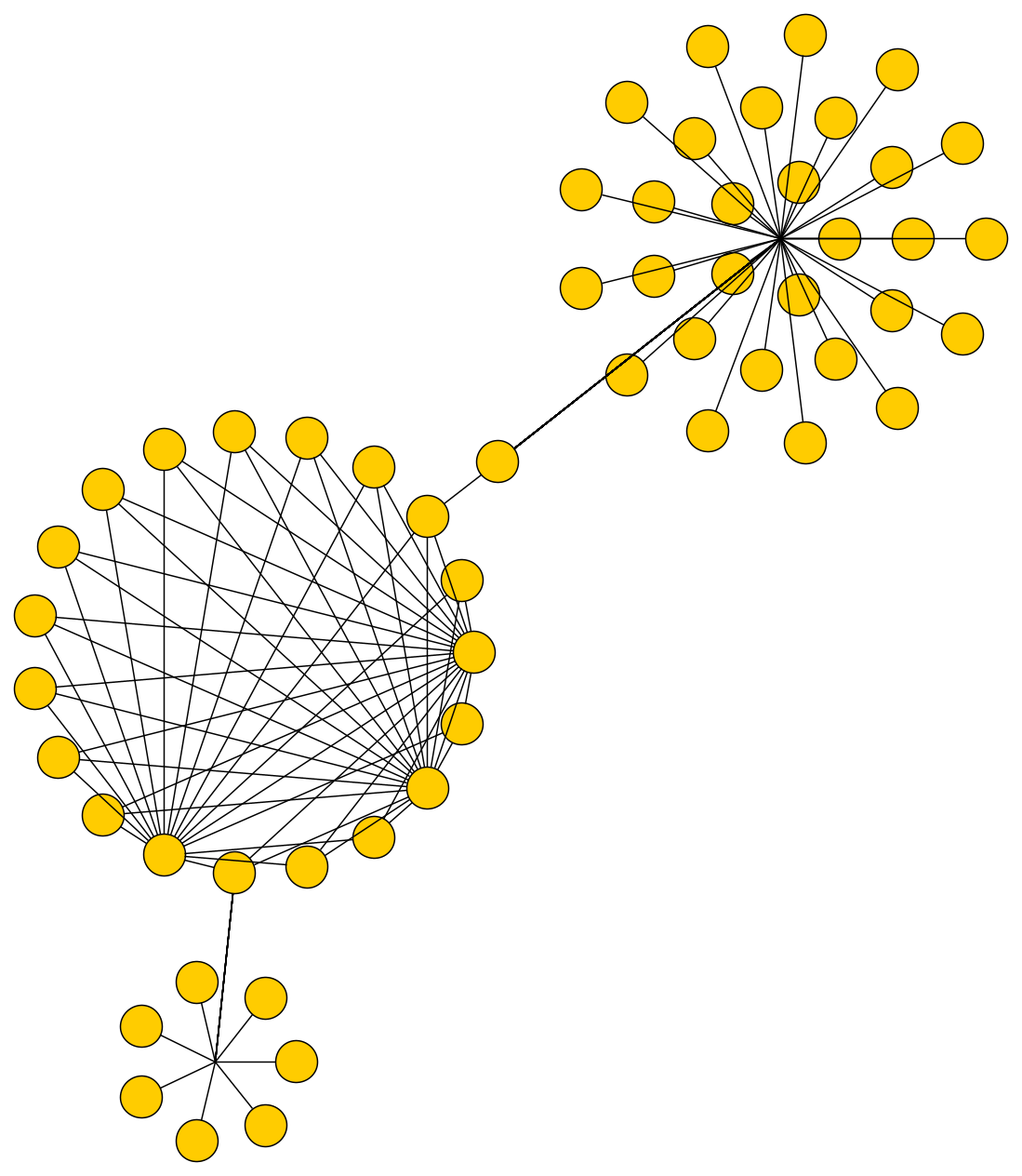
Layout of Star Substructures
The circular layout algorithm can identify star substructures in a graph and arrange them in an optimized manner, which makes them more compact and easily recognizable in the resulting layout.
To enable the identification and arrangement of star substructures, the following properties are available:
- starSubstructureStyle
- starSubstructureSize
- starSubstructureTypeSeparation
-
The properties to configure star substructures and their layout style.
As an option, the logic to identify the star substructures can take node types into account. The types can be specified via the layout data property nodeTypes.
Another option that influences the detection of star substructures is edge directedness. This means that, within a substructure, all edges need to have the same direction. To enable this option, define edgeDirectedness, which specifies the directedness for edges.
An edge can be marked using one of the following directedness values:
-
0 denotes a regular, i.e., undirected edge
-
1 denotes an edge that should be oriented from source to target
-
-1 denotes an edge that should be oriented from target to source
|
Note
|
The circular layout algorithm itself does not consider edge direction. Edge direction is only used when identifying star substructures. By default, all edges are treated as undirected. |