Tree Layouts
The yFiles tree layout algorithm family specializes in arranging tree-structured graphs. The need to visualize directed or undirected trees arises in many application areas, such as:
-
Dataflow analysis
-
Software engineering
-
Network management
-
Bioinformatics
The tree layouts are provided in two general styles:
The tree layout algorithms are designed to work with tree graphs. To handle more general graph structures, the tree layout algorithms include an TreeReductionStage, see Tree Layouts in Non-Tree Graphs for details.
The Collapsible Trees presents the setup of many tree layout algorithms in an application context. Additionally, the Layout Styles: Tree demo showcases many settings of the tree layouts.
Tree Layout
The class TreeLayout provides a general foundation for tree layouts, supporting many different styles and arrangements.
The layout process of the TreeLayout proceeds from the leaves to the root. When a node is processed, its child nodes and the subtrees originating from them are arranged by a subtree placer. These subtree placers can be customized and specified for each node individually. This flexible scheme allows you to apply completely different layout styles to the subtrees of a given tree.
The Layout Styles: Tree demonstrates various settings and styles of the TreeLayout.
Basic Options
TreeLayout delegates major aspects of layout calculation to subtree placers, which implement the interface ISubtreePlacer. They are responsible for recursively arranging a subtree’s root node together with its children (starting at the leaf nodes of a tree). The subtree placers can be specified individually for each subtree via the layout data property subtreePlacers. When arranging the subtree rooted at a node, the subtree placer specified for the local root node is used. If no subtree placer is specified, the default subtree placer accessible via the property defaultSubtreePlacer is used.
Predefined Subtree Placers
yFiles for HTML contains predefined subtree placer implementations that provide a variety of subtree arrangement schemes. The following table gives an overview of the predefined subtree placers. Note that the given descriptions assume a “canonical subtree orientation”, where child nodes are placed (more or less) below their root node. By default, the TreeLayout uses the SingleLayerSubtreePlacer.
| Class Name | Description |
|---|---|
All subtrees are placed such that a given aspect ratio for the entire tree is obeyed. |
|
Applies a composite placement scheme where two kinds of nodes are differentiated; see below for a more detailed description. |
|
Child nodes are placed evenly distributed to the left and right of their root node and also in a second line below the root node. The nodes within each line are horizontally aligned. The bus-like routing for all edges to the child nodes extends horizontally. |
|
Uses a dynamic optimization approach that chooses a placement strategy of the children such that the overall result is compact with respect to a specified aspect ratio. |
|
Subtrees are arranged in such a way that all subtrees of a single local root are aligned with their bottom border. |
|
Child nodes are placed staggered in two lines below their root node, each line containing one half of the nodes. The nodes within each line are horizontally aligned. The bus-like routing for all edges to the child nodes extends horizontally. |
|
The subtrees are kept at their current positions. They are connected by bus-like edge routes extending horizontally from the local root node. |
|
Child nodes are placed below their root node to the left and right of the downward extending bus-like routing for all edges to the child nodes. |
|
Subtrees are arranged in layers such that nodes on the same level are aligned. |
|
Child nodes are placed in multiple rows below their root node. The bus-like routing for all edges to the child nodes can be configured using the enumeration BusPlacement. Child nodes are either assigned manually to the rows using property multiLayerSubtreePlacerLayerIndices or automatically if no indices are defined. |
|
Splits the children of the local root into clusters based on port groups. The placement of the clusters is delegated to other subtree placers. |
|
Child nodes are placed horizontally aligned below their root node. The relative position of the local root node can be configured via the property rootAlignment. |
|
The children are partitioned into two subtrees that are placed on opposite sides of the local root node. The layout of the two subtrees is delegated to other subtree placers, which can be specified via the properties primaryPlacer and secondaryPlacer. |
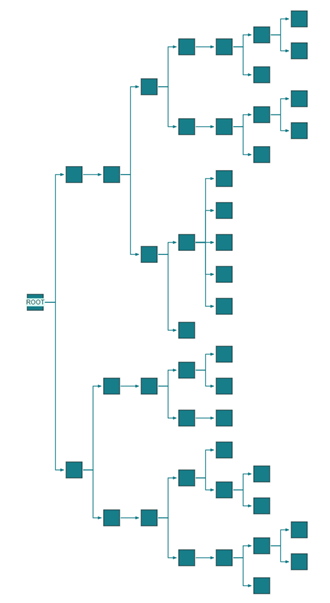
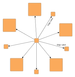
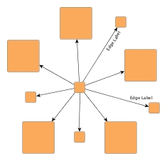
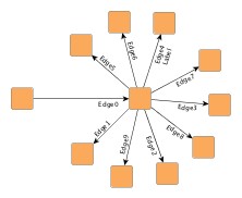
The following figure shows arrangements of an example (sub)tree using different subtree placer implementations. Note the (sub)tree’s emphasized root node.


Several subtree placers provide support for eight different subtree orientation schemes which are represented by the enumeration values of SubtreeTransform and set via transformation properties on the subtree placers. The following figure shows all orientations beginning with the so-called "canonical subtree orientation."


The class AssistantSubtreePlacer uses layout data to determine whether a node is an “assistant” or not. Assistants are placed using LeftRightSubtreePlacer, non-assistants are placed using another subtree placer which can be configured using the property childSubtreePlacer. The following figure shows two arrangements for the non-assistant nodes.


The Tree Layout allows you to interactively define subtree placers for each subtree and shows the resulting layouts.
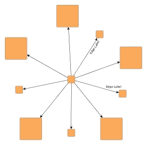
Labeling
Besides the generic labeling support described in Generic Labeling, which is available with all yFiles layout algorithms, TreeLayout also features integrated labeling for edge labels. When integrated edge labeling is enabled, TreeLayout makes space for the labels while routing the edges, ensuring they do not overlap with other objects in the diagram. The following properties can be used to influence the labeling:
- nodeLabelPlacement
-
Specifies how to handle node labels. By default, TreeLayout considers them when placing nodes and edges, but they are not moved relative to their owners.
- edgeLabelPlacement
-
Specifies how to handle edge labels. By default, TreeLayout places them as an integrated part of its layout process.
See also Integrated Labeling.
|
Tip
|
Optimal label placement with integrated labeling can be achieved using FreeEdgeLabelModel as the label model for the edges. As explained in Label Models, this edge label model is ideally suited in combination with integrated labeling and yields the best match for a label location that is computed by TreeLayout. |
Grouped Graphs
The TreeLayout supports graphs with group nodes, but each group node must contain a complete subtree. Otherwise, group nodes may overlap with each other or with nodes that are not part of the group.
Incremental Layout
The TreeLayout can consider an existing diagram as a sketch. The subtrees of a local root node are then ordered based on their locations in the sketch. This mode is enabled using the property fromSketchMode.
|
Important
|
This mode only works if the specified subtree placers implement IFromSketchSubtreePlacer. |
Sorting Child Nodes
The TreeLayout supports customizing the order of child nodes within a subtree. The layout data property childOrder provides several ways to specify the order. However, only one of these options can be used at a time.
|
Tip
|
If the desired child order is already present in an existing diagram, consider using the from-sketch mode as described in Incremental Layout. |
Port Assignment and Port Candidates
Ports are assigned by an implementation of ITreeLayoutPortAssigner. The default implementation is TreeLayoutPortAssigner, which considers port candidates specified at nodes and edges. Details on defining port candidates and the matching between port candidates defined at nodes and edges are provided in Restricting Port Locations.
Additionally, TreeLayoutPortAssigner allows you to choose between centering all ports and distributing them along one side of the node using the property mode. This setting has no effect if fixed port candidates are defined.
Moreover, the TreeLayout contains the PortPlacementStage in its layout stages. If a custom ITreeLayoutPortAssigner computes port locations that are inconsistent with the specified port candidates, the PortPlacementStage corrects the ports in a post-processing step. This correction is not necessary for the default TreeLayoutPortAssigner, though, as it handles port candidates itself.
Node Margins
By default, TreeLayout supports node margins as soon as they are declared via the layout data property nodeMargins. During layout calculation, it takes any specified additional padding around nodes into consideration and keeps the areas clear of other graph elements. The labels of a node and its adjacent edge segments are not affected and can still be placed inside or cross the node’s halo.
TreeLayout provides special support for so-called multi-parent structures, where multiple nodes share the same direct predecessor node(s) and the same direct successor node(s). It also supports multi-parent structures that are contained in group nodes. It is important, however, that all nodes belonging to the same multi-parent structure are contained in the same group node. To detect and handle these structures, special support needs to be explicitly enabled using the allowMultiParent property.
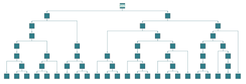
The following figure shows a graph containing multi-parent structures (the nodes in a multi-parent structure are emphasized). All nodes belonging to such a structure are placed side by side. By default, the edges incident to these nodes are routed using bus-style edge routing.
Note that the two nodes at the root of the graph also constitute a multi-parent structure: they share an “imaginary” direct predecessor.

To configure layout and drawing options of a multi-parent structure, the class MultiParentDescriptor can be used. For example, the following options can be set:
-
relative alignment of nodes within their layer
-
preferred minimum distances
-
different routing styles for edges
A MultiParentDescriptor instance can be specified for the nodes of a multi-parent structure via the layout data property multiParentDescriptors. It is important that all nodes belonging to the same multi-parent structure are assigned the same descriptor instance.
These options are available:
- minimumNodeDistance
-
Determines the minimum distance between the nodes of a multi-parent structure.
- minimumBusDistance
-
Determines the minimum distance between the nodes of a multi-parent structure and their incident edges that are routed bus-style.
- verticalAlignment
-
Determines the vertical alignment of the nodes in a multi-parent structure within their layer. Values can be set from 0.0 (top) to 1.0 (bottom). See also Vertical alignment of the nodes in a multi-parent structure.

0.0
0.5
1.0- edgeRoutingStyle
-
Configures the routing style for edges incident to the nodes of a multi-parent structure.
The following figure shows the different edge routing styles side by side:


It is important to note that the routes of edges incident to the nodes of multi-parent structures are only partially determined by the routing style configured in the MultiParentDescriptor. The other part is determined by the actual subtree placer that is used by TreeLayout.
With regard to edge routing, the SingleLayerSubtreePlacer yields the best results in conjunction with multi-parent structures. Multi-parent support also harmonizes well with BusSubtreePlacer, LeftRightSubtreePlacer, and DendrogramSubtreePlacer. However, the following options of SingleLayerSubtreePlacer are not supported in conjunction with multi-parent structures:
-
routing style option ORTHOGONAL_AT_ROOT
-
root alignment options LEADING_ON_BUS and TRAILING_ON_BUS
Also with regard to edge routing, certain aspects of port candidate configurations at nodes in multi-parent structures will be ignored to prevent situations where this would lead to confusing (or even conflicting) edge routes in the resulting layout. In particular, this applies to the side specified by a port candidate of an incident edge: the edge is instead always routed in flow direction. Note that as described in section Port Assignment and Port Candidates the PortPlacementStage will move the ports in a post-processing step, which may lead to undesirable edge paths. It is recommended to not define port candidates for the edges at nodes in multi-parent structures. All nodes of a multi-parent structure should yield the same port assigner, if any.
Improving the Compactness of Layout Results
Besides the chosen subtree placers, the compactness of the layout also depends on the selected distances and spacing values. The following figure shows the possible impact of such properties.
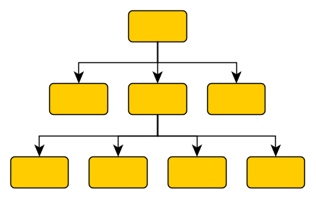
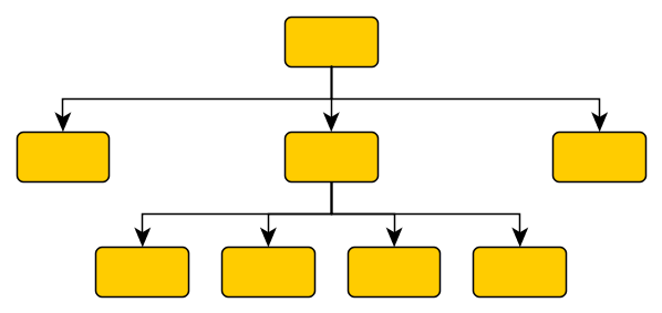
Note that in the less compact figure, placing the nodes of the second layer closer together would violate the specified vertical distance. More precisely, the vertical distance between the leftmost/rightmost node and the horizontal bus-like edge segments of the subtree rooted at the middle node would be violated. Recall that this distance is used between nodes and between nodes and other subtree elements like edges and labels.
The table Suitable choice of spacing values gives some hints on how to choose the distances/spacing values such that the results are more compact.
|
Note
|
The suggested hints only apply to the orthogonal routing style. |
| Subtree Placer | Value |
|---|---|
The value of property minimumFirstSegmentLength should be at least verticalDistance. |
|
The value of property minimumFirstSegmentLength should be at least verticalDistance. |
|
The value of the product of layerSpacing multiplied by busAlignment should be at least spacing. |
Radial Tree Layout
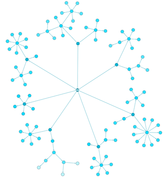
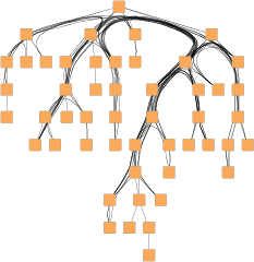
The class RadialTreeLayout is a tree layout algorithm that arranges the subtrees originating from a node in a radial fashion around that node. It is well-suited for large trees (for example, those with 10,000 nodes) because it computes layouts quickly and compactly.
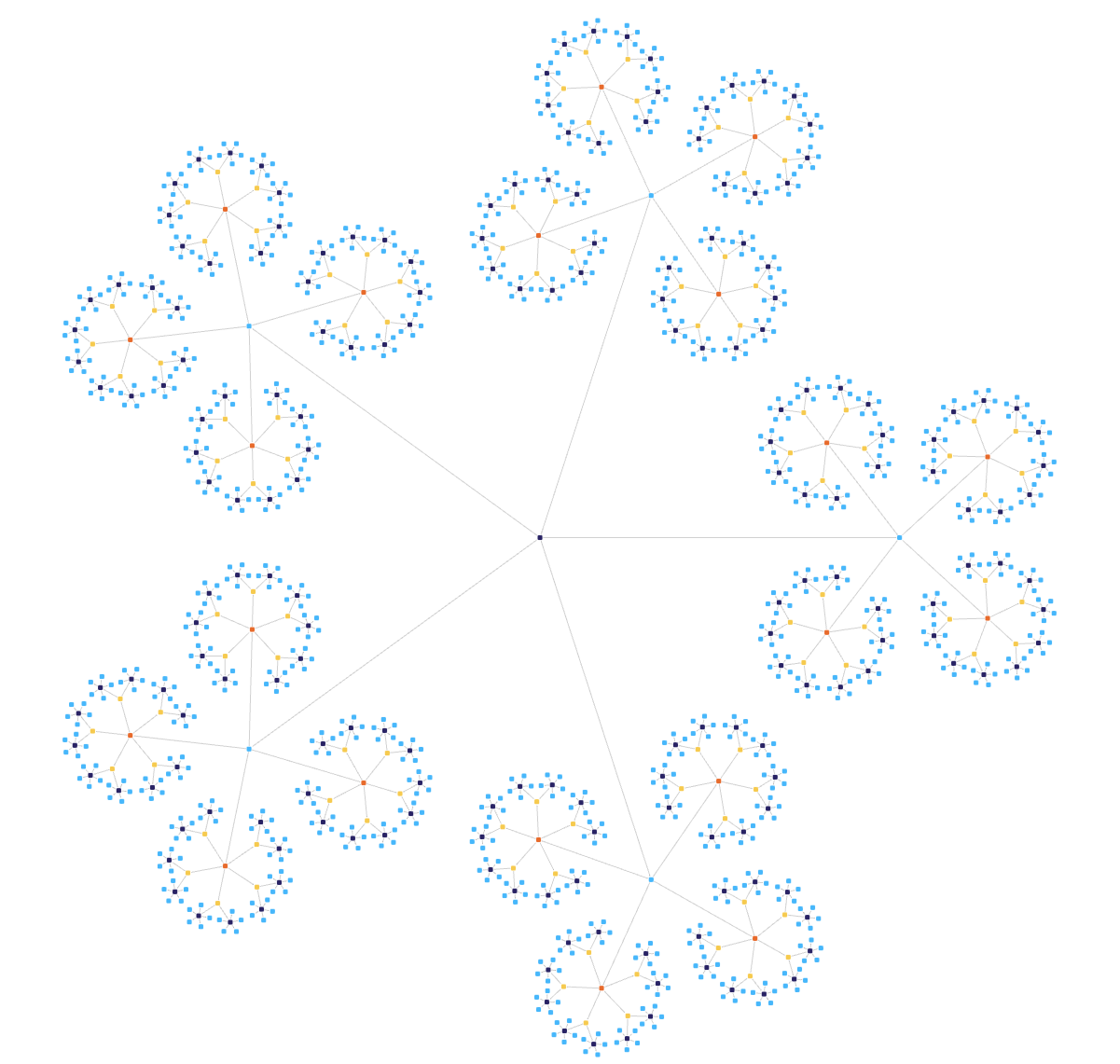
The Large Collapsible Tree shows how to display large graphs laid out with the RadialTreeLayout. The Layout Styles: Radial Tree showcases the various settings of the RadialTreeLayout.
Basic Options
These options configure class RadialTreeLayout in detail.
- rootSelectionPolicy
-
Determines which node will be used as the root of the tree. The available options are:
- DIRECTED_ROOT
-
Chooses a node with an indegree of zero, if one exists. A good choice for directed rooted trees.
- CENTER_ROOT
-
Chooses the root such that the depth of the resulting tree is minimized.
- WEIGHTED_CENTER_ROOT
-
Chooses the root such that the number of paths between any two nodes that traverse the root is maximized. A good choice for undirected trees.
- preferredRootSectorAngle
-
This setting determines the angular range of the sector that will be reserved around the root node of the graph to accommodate the attached subtrees.
- preferredChildSectorAngle
-
This setting determines the angular range of the sector that will be reserved for the children of a root node. The possible angular range is between 1 and 359 degrees. The remaining angular range (360 minus x) will be automatically used to accommodate the edge that connects to the root node. The smaller the chosen value, the more the nodes appear to be driven away from their root nodes and the center of the graph. Typically, the compactness of the layout will decrease with smaller values. Values close to 1 will lead to layouts that consume a lot of space.
- minimumEdgeLength
-
Determines the minimum length of an edge. The smaller the chosen value, the more compact the resulting layout.
- compactnessFactor
-
This parameter influences the length of the tree edges as it is computed by the layout algorithm. The larger the compactness factor, the shorter the tree edges and the more compact the overall layout. Larger compactness factors may result in longer running times.
- interleavedNodes
-
Child nodes at the same parent tree node can be placed in an interleaving fashion. Especially if some tree node has many child nodes and if they have similar sizes, the diagram can become more compact. The nodes specified via this layout data property may be interleaved.


|
Note
|
If there is enough space to place the child nodes of a tree node without interleaving, they will be placed normally, even if they are part of the interleaved nodes. |
- childAlignmentPolicy
-
Determines the policy for aligning the child nodes at a tree node. The available options are:
- PLAIN
-
Child nodes at the same parent tree node are aligned such that each child node has the same border-to-border distance to the parent node. When interleaved child node placement is active, two different distances will be realized.
- SAME_CENTER
-
Child nodes at the same parent tree node are aligned such that each child node has the same center-to-center distance to the parent node. Therefore, all nodes will be placed on one common radius around their root. When interleaved child node placement is active, two different radii will be realized.
- COMPACT
-
Child nodes at the same parent tree node are aligned such that the resulting drawing will be as compact as possible, not considering any symmetric constraints. This is the default setting.
- SMART
-
Child nodes at the same parent tree node are aligned using a heuristic for a well-balanced and symmetric layout. When interleaved child node placement is active, plain alignment will be used instead of the heuristic.
- chainStraighteningMode
-
If activated, all nodes in a chain will be placed on a straight line. This may lead to smoother and more symmetric layouts. By default, this feature is turned off.
- allowOverlaps
-
If activated, this option further increases the compactness of the resulting layout, but nodes may overlap slightly.
Labeling
Besides the generic labeling support as described in Generic Labeling, which is available with all yFiles layout algorithms, RadialTreeLayout also features integrated labeling.
Integrated labeling is available for node labels and edge labels. These labels are considered when determining the positions for the nodes of the tree. With this strategy, it is guaranteed that no label will overlap other objects in the diagram. See also Integrated Labeling.
Enabling the integrated node labeling support of the RadialTreeLayout means that each node label will be placed and arranged by the RadialTreeLayout so that there are no overlaps of node labels with each other or with graph elements (other than their respective node).
- nodeLabelPlacement
-
Determines how the layout algorithm handles node labels.
- edgeLabelPlacement
-
Determines how the layout algorithm handles edge labels.
The RadialTreeLayout supports different node labeling policies that can be configured using the nodeLabelPlacement property. The following policies are available:
- HORIZONTAL
-
Each node label is placed at the center of its node, with a horizontal orientation. Multiple node labels will be placed center aligned and stacked.
- RAY_LIKE
-
Node labels of leaf nodes and node labels of nodes having exactly one successor are oriented ray-like, i.e., with the same orientation as their node’s incoming edge. Additionally, the node labels of leaf nodes are placed outside their node. Multiple, ray-like oriented node labels are left aligned. Node labels of nodes having more than one successor are placed at the center of their node, with a horizontal orientation. See also below.
- RAY_LIKE_LEAVES
-
Node labels of leaf nodes will be oriented ray-like, i.e., with the same orientation as their node’s incoming edge. Additionally, these node labels will be placed outside their node. Other node labels will be placed at the center of their node, with a horizontal orientation. See also below.
- GENERIC
-
Node labels are placed by the generic labeling support.
- CONSIDER
-
Node labels are considered but not placed by the layout algorithm.
- IGNORE
-
Node labels are ignored.
Note that ray-like oriented node labels are only supported by integrated labeling for node labels that use a “free” label model, e.g., FreeNodeLabelModel.
Enabling the integrated edge labeling of the RadialTreeLayout instructs the algorithm to find optimal placements for edge labels so that there are no overlaps of edge labels with each other or with graph elements. Also, the RadialTreeLayout orients and arranges the edge labels.
Note that edge label placement configurations with the EdgeLabelPreferredPlacement descriptors are currently only partially supported by the integrated edge labeling of the RadialTreeLayout. Placement of the edge label at a specified preferred side of the edge can be guaranteed. Preferred placement of the edge label at the source node or target node, however, cannot be guaranteed entirely.
|
Tip
|
Optimal label placement with integrated edge labeling can be achieved using the FreeEdgeLabelModel as the label model for the edge labels. As explained in Label Models, this edge label model is ideally suited in combination with integrated edge labeling and yields the best match for a label location that is computed by the RadialTreeLayout. |
Incremental Layout
The RadialTreeLayout can consider the current diagram when calculating a new layout. This is enabled by setting the childOrderingPolicy to FROM_SKETCH.
|
Note
|
If a custom child order is defined via the layout data property childOrder, the sketch is ignored. |
Sorting Child Nodes
The RadialTreeLayout supports multiple predefined policies that determine the order of a node’s children. These policies are configured using the childOrderingPolicy property.
In addition, you can define a custom order using the layout data property childOrder. This property offers multiple ways to define the order, but only one option can be used at a time.
|
Tip
|
When the desired order of the children is already present in an existing diagram, consider using the from-sketch mode by setting the child order policy to FROM_SKETCH, as described in section Incremental Layout. |
Node Margins
By default, RadialTreeLayout supports node margins as soon as they are declared using the Layout Data property nodeMargins. The layout considers any specified additional padding around nodes. However, because the edges are routed as straight lines, they may cross through these areas in the resulting diagram. Node margins may overlap if the option allowOverlaps is enabled.
Tree Layouts in Non-Tree Graphs
The TreeLayout and RadialTreeLayout algorithms are designed to compute layouts of tree graphs. However, both layout algorithms include the TreeReductionStage in their layout stages, which enables them to handle arbitrary graph structures. This stage is accessible through the treeReductionStage property on the layout algorithm.
Before the core of the tree layout algorithms is run, this stage temporarily removes edges from the graph until the remainder is a tree or a forest. This subgraph is then arranged by the core tree layout algorithm. Afterward, the removed edges are routed by an edge routing algorithm. Optionally, the labels are placed using the generic labeling support.
- nonTreeEdgeRouter
-
The router that is used to route the edges that are not handled by the core tree layout algorithm. By default, the edges are routed as straight lines.
- nonTreeEdgeLabeling
-
The labeling algorithm that is used to label the edges that are not handled by the core tree layout algorithm.
|
Tip
|
If the non-tree edges should blend in with the edges handled by the core tree layout algorithm, it is advisable to specify similar routing styles for both. Also, increasing the minimum distances of the subtree placers helps ensure that there is enough space for the non-tree edges. When using the EdgeRouter together with a tree layout that produces monotonic edge paths, the monotonic path restriction may be used to restrict the paths of the non-tree edges in the same way. |
Edge Bundling
Instead of routing the edges with a dedicated edge routing algorithm, the TreeReductionStage allows to bundle the non-tree edges. With this routing style, the paths of the non-tree edges in a diagram are bundled so that they follow similar routes.
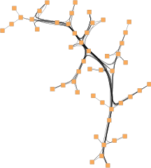
Using edge bundling significantly reduces the visual clutter in drawings of large graphs with many edges. It highlights high-level patterns of edge routes and relations between different groups of nodes so that they can be recognized easily. Edge bundling is commonly used in bioinformatics, social network analysis, telecommunications, and fraud detection. The Edge Bundling shows edge bundling in multiple layout styles.
To configure edge bundling the TreeReductionStage provides the edgeBundling property which holds an instance of EdgeBundling. This EdgeBundling instance, in turn, holds an instance of the EdgeBundleDescriptor class to store and retrieve default edge bundling values for non-tree edges. It can be accessed via the defaultBundleDescriptor property.
In addition to the instance held by EdgeBundling, edge bundling descriptors can also be associated with single non-tree edges to specify individual settings for them. To this end, the layout data classes of the tree layout algorithms offer the edgeBundleDescriptors property.
The classes EdgeBundling and EdgeBundleDescriptor provide the means to configure drawing options related to the edge bundling support in the TreeReductionStage.
To configure the global edge bundling settings, class EdgeBundling provides the following properties:
- EdgeBundling.bundlingStrength
-
Determines the tightness of the edge bundles. It takes values from the interval [0.0, 1.0], where 0.0 corresponds to straight-line, non-bundled edges and 1.0 to strongly bundled edges. For good readability featuring clearly visible bundles, a bundling strength greater than 0.8 is recommended.
- EdgeBundling.bundlingQuality
-
Determines the quality of the edge bundling. Higher values require more sophisticated methods to calculate the bundles and, thus, the running time can significantly increase. The setting can take values from the interval [0.0, 1.0]. For large graphs, values smaller than 0.2 are recommended.
- EdgeBundleDescriptor.bundled
-
Determines whether the edge is bundled.
- EdgeBundleDescriptor.considerDirection
-
Determines if the direction of an edge should be taken into consideration. If enabled, incoming and outgoing edges incident to a node are bundled separately.
- EdgeBundleDescriptor.bezierFitting
-
Determines whether the path of an edge should be approximated by a cubic Bézier curve. The approximation may significantly reduce the number of bends.