Orthogonal Layout
Class OrthogonalLayout is a versatile layout provider for undirected graphs. It generates clear representations of complex networks and is especially well-suited for application areas such as:
-
Software engineering
-
Database schemas
-
System management
-
Knowledge representation
The orthogonal layout algorithm follows the topology-shape-metrics approach and consists of three phases:
-
The first phase calculates edge crossings in the drawing.
-
The second phase computes the bends in the drawing.
-
The third phase determines the final coordinates.
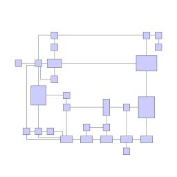
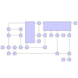
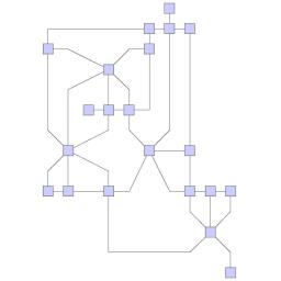
The layout algorithm is well-suited for medium-sized sparse graphs. It produces compact drawings with no overlaps, few crossings, and few bends.
Basic Options
The global layout style of OrthogonalLayout is set using the layoutMode property. Available options are:
- STRICT
-
This mode produces orthogonal edge routes and maintains the original node size. It also supports features like node margins and labels, which are not supported by the other modes.
- FORCED_STRAIGHT_LINE
-
This mode tries to force straight-line edge routes by changing the size of the nodes accordingly. Features like labels and node margins are not supported.
- RELAXED
-
This mode produces edge routes where the first or last segment of an edge may be non-orthogonal. Features like labels and node margins are not supported.
|
Important
|
The layout style settings are ignored for grouped graphs and oriented orthogonal layouts. Orthogonal layouts with one of these features enabled always use mode STRICT. |
- gridSpacing
-
Defines the virtual grid spacing used by the layout algorithm. Each node is placed in such a way that its center point lies on a grid point. Edges are routed in such a way that their segments lie on grid lines, if the terminal nodes of the edges allow the ports to be placed accordingly. Note that this option is only guaranteed to be obeyed for mode STRICT, for all other layout modes it is used as a hint only.
- uniformPortAssignment
-
If enabled, the algorithm may insert additional bends to obtain a more uniform port assignment of edges incident to the same node side.
- stopDuration
-
Specifies the preferred time limit. This setting is useful to restrict the running time of orthogonal layout. If there is a time limit, the algorithm may automatically disable some of the optimization settings mentioned above. Restricting the running time may result in lower layout quality. Furthermore, the real runtime may exceed the specified duration since the layout algorithm still has to find a valid solution.
- fromSketchMode
-
If enabled, the layout algorithm interprets the initial graph layout as a sketch for the desired outcome of the layout process. The layout algorithm tries to orthogonalize the given sketch without making too many modifications with respect to the original drawing.
- defaultEdgeDescriptor
-
Class OrthogonalLayoutEdgeDescriptor can be used to specify further edge-related layout options. In addition to the instance held directly by OrthogonalLayout, layout descriptors can also be associated with single edges to specify individual settings for them. Setting individual descriptors for edges is done through layout data property edgeDescriptors.
OrthogonalLayout by default also supports node margins as soon as they are declared using nodeMargins. Furthermore, it is possible to define individual crossing costs and bend costs for each edge, which allows you to treat some edges as more important than others. These costs are defined via the according layout data properties, see edgeCrossingCosts and edgeBendCosts.
Labeling
Integrated labeling is available for edge labels and can be used with STRICT. The labels are considered when determining both node placement and edge path generation. Using this strategy ensures that no edge label will overlap other objects in the diagram.
Integrated labeling can be enabled or disabled using the property edgeLabelPlacement.
|
Tip
|
Optimal label placement with integrated labeling can be achieved using FreeEdgeLabelModel as the label model for the edges. This edge label model is ideally suited in combination with integrated labeling and yields the best match for a label location that is computed by OrthogonalLayout. |
OrthogonalLayout provides support for node label-aware layout, which can be enabled via the property nodeLabelPlacement. Node labels are not actively placed, but their sizes are considered for the placement of adjacent graph elements. Considering node labels during layout calculation guarantees that they will not overlap nodes in the diagram.
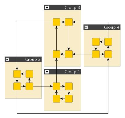
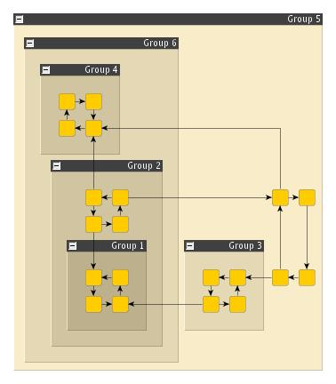
Grouped Graphs
The OrthogonalLayout supports the layout of grouped graphs. The algorithm calculates both the position and dimension of group nodes.
Parts of a graph that belong to the same group will be placed so that they share a common rectangular area in the layout space. The algorithm calculates the positions and sizes of these group nodes.
The layout algorithm is well-suited for medium-sized sparse graphs. It produces compact drawings with no overlaps, few crossings, and few bends.
|
Important
|
Some features like oriented edges, substructures, and the from-sketch mode (see property fromSketchMode) are not available when using grouped graphs. |
Substructure Support
OrthogonalLayout can process several graph substructures in a specific way. The goal of this feature is to emphasize particular structures by arranging them in an optimized fashion. Emphasizing substructures can significantly improve the readability and clarity of orthogonal layouts. You can choose from multiple styles for each type of substructure. Currently, support for tree, chain, and cycle structures is available.

Settings related to substructures and their styles are available directly on the OrthogonalLayout instance.
|
Important
|
The substructure feature works in conjunction with directed edges but is disabled if the graph has group nodes. |
Substructures - Node Types
You can define node types to enable the detection of substructures. This is done via the layout data property nodeTypes. Substructures can only contain nodes of the same type.
Substructures - Edge Directedness
It is possible to define the directedness of an edge for the detection of substructures using the layout data property edgeDirectedness. This property allows you to specify the directedness as a floating-point value, which is interpreted as follows:
-
0: undirected edge
-
1: edge is directed from the source to the target node
-
-1: edge is directed from the target to the source node (reverse directed)
The directedness feature provides more control over which structures the algorithm should handle explicitly. A substructure is only detected if all edges are either undirected or consistently directed with respect to the direction value. If no custom directedness is specified, an edge is considered undirected.
|
Important
|
The edge directedness described here must not be confused with the Oriented Edge Drawings feature. The directedness value is solely used in conjunction with the detection of substructures. |
Tree Substructures
The available styles for tree substructures are shown in the following figures. You can configure the style using the property treeSubstructureStyle.


Other settings related to tree substructures are (see the API documentation for more details):
|
Tip
|
The general style of the two tree layout styles DEFAULT and INTEGRATED is quite similar. The difference lies in the internal approach. For the default style, a dedicated tree layout algorithm is applied to the tree structure and the computed layout is inserted into the orthogonal layout of the rest of the graph. In contrast, the integrated approach models the tree style internally, using the orthogonal layout framework. The integrated style can consequently lead to results where the overall layout is more homogeneous and the grid is perfectly considered. However, the default approach might yield more compact layouts where trees are easily recognizable due to the highly different arrangement style. |
Chain Substructures
The figures below illustrate the supported chain layout styles. You can configure the style using the chainSubstructureStyle property.


In addition, you can define the minimum size (number of nodes) a chain must have to be explicitly handled as a substructure. Use the chainSubstructureSize property for this.
Cycle Substructures
The figures below illustrate the supported layout styles for cycle substructures. You can specify the style using the cycleSubstructureStyle property.


You can also define the minimum size (number of nodes) a cycle must have to be explicitly handled as a substructure. Use the cycleSubstructureSize property to define the minimum size..
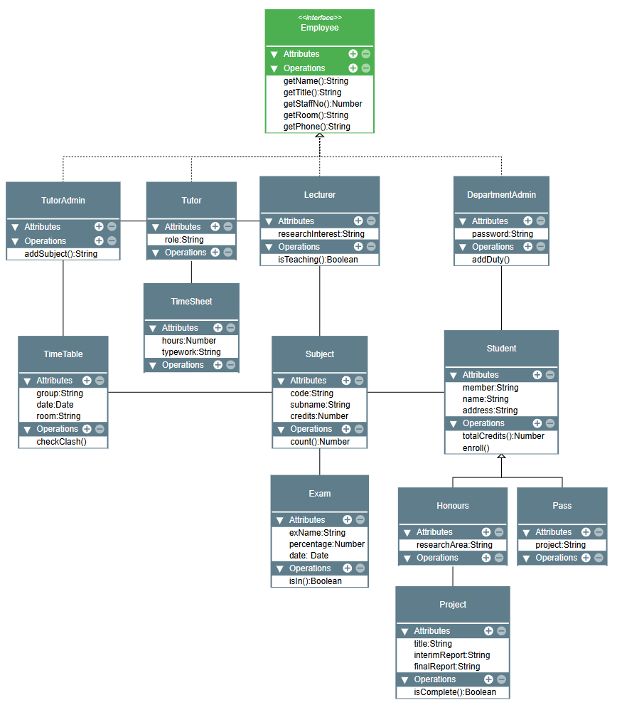
Oriented Edge Drawings
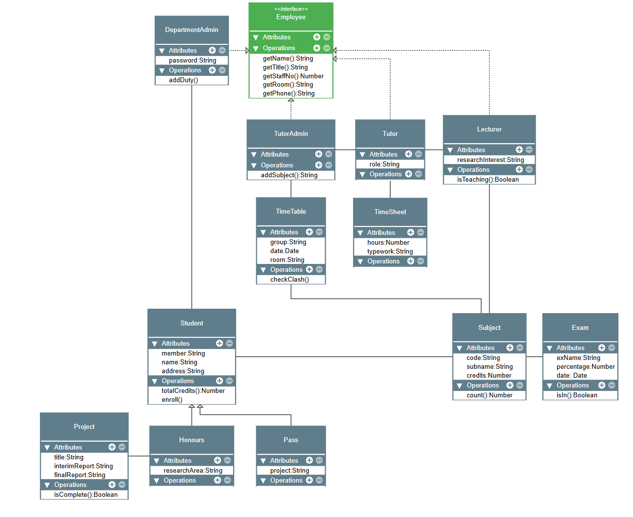
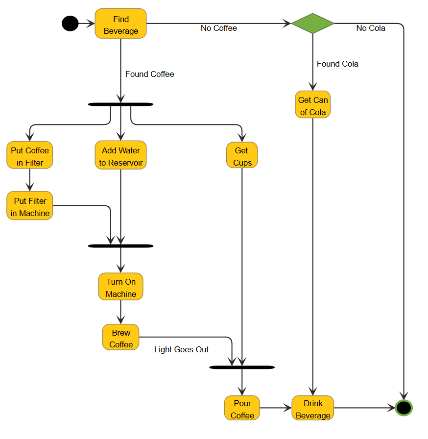
The OrthogonalLayout optionally supports oriented edge drawings, but not when used with hierarchically nested graphs or a non-default value of the layoutMode. Oriented orthogonal drawings are useful in application domains such as software engineering, database schema design, and system management.
It supports advanced edge path generation with respect to:
-
the main layout orientation, which is a predefined orientation, such as bottom-to-top, and
-
using a common anchor point and common edge segments for edges that connect to a common node.
The latter is also referred to as edge/port grouping, which is described in Edge and Port Grouping.
These features together enable high-quality graph layouts that are a perfect match for UML-style class diagrams, for example. The layout algorithm is well suited for medium-sized graphs where a subset of edges should be routed with respect to the main layout orientation. It produces compact drawings with no overlaps and few crossings.
|
Important
|
This feature is not available with grouped graphs. If a graph has group nodes, this feature is disabled. In that case, it is recommended to use the Hierarchical Layout algorithm instead. |
You can specify a subset of oriented edges that should be routed with respect to the main layout orientation by means of layout data property edgeOrientation. The main orientation is controlled via the property layoutOrientation.
Moreover, you can specify the edge groups using sourceGroupIds and targetGroupIds. The setup of edge groups is described in Edge and Port Grouping.