Port Placement
The points where an edge connects to its source and target nodes are called ports. In some applications they are of importance and have a fixed position, sometimes even a visual representation. In other applications they can be completely ignored. Similarly, some layout algorithms take care to distribute the ports in a way which fits their criteria best, whereas other algorithms simply place them in the middle of the node.
Internally, the layout algorithms are not aware of ports. They might place the start and end points of edges, though. Further, these locations might be restricted or some rules can be defined to restrict them
In this section we describe how we can control the port placement of automatic layout algorithms. Note that the layout executor can already apply many rules with simple settings.
Automatic Port Handling by LayoutExecutor
While ports are part of the model in the view part the layout algorithms don’t handle them automatically. LayoutExecutor, however, provides some settings to make the layout algorithms aware of them.
Keeping the Port Location
Setting fixPorts to true keeps the location of the ports fixed
(relative to the node layout). This can be used in cases where the ports are already placed in a fixed location
on the nodes and should not be altered. Technically, if this mode is enabled the LayoutExecutor
automatically creates strong port constraints at the current location.
This setting is ignored if port constraints are already registered.
This feature has no effect for layout algorithms which don’t support port constraints. For these algorithms a FixPortLocationStage has to be added. See also Using fixPorts with organic layout.
This feature is disabled by default
Grouping Edges which Connect to the Same Port
One single port can be source or target of an arbitrary number of edges. However, since the layout algorithms
are not aware of ports they might place these points at different locations.
Setting automaticEdgeGrouping to true
automatically groups edges that are connected to the same port.
This setting is ignored if edge groups are already registered.
This feature is enabled by default.
Placing Ports on the Node’s Outline
The layout algorithms treat nodes as rectangular objects whose bounds are defined by their layout. Therefore, the layout algorithms place the ports either at the border or the center of a node. Nodes, however, might be visualized by more complex shapes. Setting the portAdjustmentPolicy enables LayoutExecutor to place ports at the outline of a node. The first or last segment of the connecting edge will be prolonged or shortened to connect to that port.
This setting is ignored if strong port constraints are set.
This feature is disabled by default (i.e. set to NEVER).
Placing Port Labels
Since the layout algorithms are not aware of ports the automatic label placement is not aware of port labels, either. However, ports are bound to nodes and the end points of edges. Therefore, their labels can be mimicked either as node labels or as edge labels. LayoutExecutor automatically handles this conversion task. Since the best way to convert port labels might vary from port to port the policy for that is defined in an ItemMapping<TItem,TValue> for each single port. The mapping is set using property portLabelPolicies.
Restricting Port Locations
To restrict the location where an edge connects to its source or target node to specific locations during automatic layout, yFiles for HTML provides the concept of port candidates. This concept is implemented by the PortCandidate class. Port candidates can be used in conjunction with both nodes and edges.
Port Candidates for Nodes
When used in conjunction with nodes, port candidates provide a means to:
- Restrict anchor locations at nodes. You can specify either exact anchor locations at a node (called location constraints or strong constraints) or restrict the anchor to any location at a specific side of a node (called side constraints or weak constraints).
- Associate costs with a given anchor location. This establishes an order of precedence among a given set of anchor locations. Anchor locations with low cost are favored over anchor locations with higher costs.
- Limit the number of connecting edges at a given anchor location.
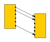
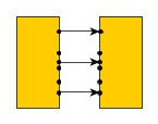
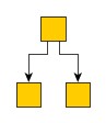
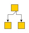
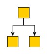
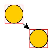
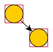
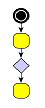
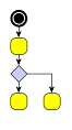
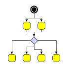
A typical example for the use of port candidates is a flow diagram as shown in Using port candidates to control connection points: The diamond shape, which is the visualization of a switch, should have its incoming edge connecting at the top. The first outgoing edge should connect at the bottom (first image), the second at the right, the third at the left (second image). If there are more outgoing edges, these edges should connect at the bottom as well as more than one incoming edge should connect at the top (third image).
To define the set of side constraints and location constraints at a node, multiple port candidates can easily be combined using the services of the PortCandidateSet class. When a PortCandidate object is added to an instance of PortCandidateSet, the capacity of the port candidate can optionally be configured. The capacity of a given port candidate (sometimes also referred to as cardinality) specifies the allowed number of connecting edges at that side or anchor location.
Matching Port Candidates and Edges
Matching port candidates means the process of distributing a node’s edges to the available port candidates. If a node is associated with a set of port candidates via a PortCandidateSet object, all edges connecting to that node are distributed among the available port candidates with respect to:
- the costs of a given port candidate
- the number of edges that are allowed to connect to a given port candidate
For example, when the limit of allowed edges for a given port candidate with costs k is reached, i.e., the given port candidate is said to be saturated, then the next least expensive port candidate among the remaining ones is chosen to connect edges to.
Defining a port candidate set demonstrates how to create a candidate set for the diamond node shown in Using port candidates to control connection points: First, port candidates for the four corners of the diamond are defined. The number of connecting edges for these candidates is limited to 1.
Further port candidates, which can take an unlimited number (Integer.MAX_VALUE)
of edges, are defined to handle any additional edges.
To let the edges first connect to the corners before the additional candidates are
occupied, a higher cost is associated with these latter candidates.
// define a PortCandidateSet
const pcs = new PortCandidateSet()

// the node has the size (30, 30) with the point (0, 0) at the center
// so the coordinates for the top corner are (0, -15)

// create a candidate at the top corner with direction North and cost 0
const candidate = PortCandidate.createCandidate(0, -15, PortDirections.NORTH, 0)
// add it to the set and allow only one edge to connect to it
pcs.add(candidate, 1)
// do the same for the other three corners
pcs.add(PortCandidate.createCandidate(0, 15, PortDirections.SOUTH, 0), 1)
pcs.add(PortCandidate.createCandidate(15, 0, PortDirections.EAST, 0), 1)
pcs.add(PortCandidate.createCandidate(-15, 0, PortDirections.WEST, 0), 1)

// to allow more edges to connect at the top and bottom
// create extra candidates and allow Integer.MAX_VALUE edges to connect

// to avoid that these candidates are occupied before the others
// associate a cost of 1 with them
pcs.add(PortCandidate.createCandidate(0, -15, PortDirections.NORTH, 1), Number.MAX_VALUE)
pcs.add(PortCandidate.createCandidate(0, 15, PortDirections.SOUTH, 1), Number.MAX_VALUE)
To influence the matching process, a subset of the PortCandidate objects used for a node can additionally be associated with the respective ports of its connecting edges. The subset then defines a restricted set of desired port candidates an edge prefers to connect to. The PortCandidate objects can be combined using ICollection<T> objects which are stored by means of layout data or data providers. The data providers are registered with the graph using the look-up keys SOURCE_PORT_CANDIDATE_COLLECTION_DP_KEY and TARGET_PORT_CANDIDATE_COLLECTION_DP_KEY.
Layout support for port candidates lists the layout algorithms that provide support for port candidates.
| Layout Style | Class Name | Note |
|---|---|---|
Declaring port candidates for a node is done by associating a corresponding PortCandidateSet object with the node via layout data or the data provider key NODE_PORT_CANDIDATE_SET_DP_KEY. All layout and edge routing styles that support port candidates respect these restrictions without further configuration.
/**
 * @param {!IGraph} graph
 * @param {!PortCandidateSet} portCandidateSet
 */
function performLayoutWithNodePortCandidates(graph, portCandidateSet) {
  // use LayoutData to configure the port candidates
  const layoutData = new HierarchicLayoutData({
    nodePortCandidateSets: (node) =>
      node.tag === 'diamond' ? portCandidateSet : null
  })

  // and perform a layout
  const layout = new HierarchicLayout()
  graph.applyLayout(layout, layoutData)
}function performLayoutWithNodePortCandidates(graph: IGraph, portCandidateSet: PortCandidateSet): void {
  // use LayoutData to configure the port candidates
  const layoutData = new HierarchicLayoutData({
    nodePortCandidateSets: (node: INode) => (node.tag === 'diamond' ? portCandidateSet : null)
  })

  // and perform a layout
  const layout = new HierarchicLayout()
  graph.applyLayout(layout, layoutData)
}
Port Candidates for Edges
Similar to nodes, when used in conjunction with edges, port candidates provide a means to:
- Restrict anchor locations at the source or target node of an edge. You can specify either exact anchor locations at a node (called location constraints or strong constraints) or restrict the anchor to any location at a specific side of a node (called side constraints or weak constraints).
- Associate costs with a given anchor location. This establishes an order of precedence among a given set of anchor locations. Anchor locations with low cost are favored over anchor locations with higher costs.
Unlike node port candidates, there is no point in specifying the number of edges at an anchor location since edge port candidates are defined per single edge. Consequently, edge port candidates are combined with regular Collection objects instead of PortCandidateSet.
The following layout style supports edge port candidates:
| Layout Style | Class Name | Note |
|---|---|---|
A special case is RecursiveGroupLayout which delegates to other layout algorithms and therefore supports port candidates if these do.
In particular, this scheme is supported by edge routing algorithms, and it allows to conveniently specify side constraints comprising two or three sides, for example.
Routing support for port candidates lists the edge routing algorithms that provide support for port candidates modeling enhanced port constraints.
| Routing Style | Class Name | Note |
|---|---|---|
Declaring port candidates for the source or target of an edge is done by associating a corresponding Collection of PortCandidate objects with the edge via layout data or the data provider key SOURCE_PORT_CANDIDATE_COLLECTION_DP_KEY or TARGET_PORT_CANDIDATE_COLLECTION_DP_KEY, respectively. All layout and edge routing styles that support port candidates respect these restrictions without further configuration.
/**
* @param {!IGraph} graph
*/
function performLayoutWithEdgePortCandidates(graph) {
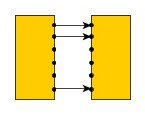
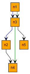
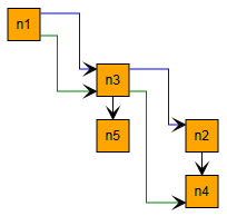
// blue edges should start near the right upper corner and end near the left upper corner
const blueSourcePC = new List({
items: [PortCandidate.createCandidate(15, -10, PortDirections.EAST)]
})
const blueTargetPC = new List({
items: [PortCandidate.createCandidate(-15, -10, PortDirections.WEST)]
})
// green edges should start near the right lower corner and end near the left lower corner
const greenSourcePC = new List({
items: [PortCandidate.createCandidate(15, 10, PortDirections.EAST)]
})
const greenTargetPC = new List({
items: [PortCandidate.createCandidate(-15, 10, PortDirections.WEST)]
})
// use LayoutData to apply the source and target port candidates
const layoutData = new HierarchicLayoutData({
sourcePortCandidates: (edge) =>
edge.tag === 'blue'
? blueSourcePC
: edge.tag === 'green'
? greenSourcePC
: null,
targetPortCandidates: (edge) =>
edge.tag === 'blue'
? blueTargetPC
: edge.tag === 'green'
? greenTargetPC
: null
})
// and perform a layout
const layout = new HierarchicLayout()
graph.applyLayout(layout, layoutData)
}function performLayoutWithEdgePortCandidates(graph: IGraph): void {
// blue edges should start near the right upper corner and end near the left upper corner
const blueSourcePC = new List<PortCandidate>({
items: [PortCandidate.createCandidate(15, -10, PortDirections.EAST)]
})
const blueTargetPC = new List<PortCandidate>({
items: [PortCandidate.createCandidate(-15, -10, PortDirections.WEST)]
})
// green edges should start near the right lower corner and end near the left lower corner
const greenSourcePC = new List<PortCandidate>({
items: [PortCandidate.createCandidate(15, 10, PortDirections.EAST)]
})
const greenTargetPC = new List<PortCandidate>({
items: [PortCandidate.createCandidate(-15, 10, PortDirections.WEST)]
})
// use LayoutData to apply the source and target port candidates
const layoutData = new HierarchicLayoutData({
sourcePortCandidates: (edge) => (edge.tag === 'blue' ? blueSourcePC : edge.tag === 'green' ? greenSourcePC : null),
targetPortCandidates: (edge) => (edge.tag === 'blue' ? blueTargetPC : edge.tag === 'green' ? greenTargetPC : null)
})
// and perform a layout
const layout = new HierarchicLayout()
graph.applyLayout(layout, layoutData)
}
Port Constraints
A port constraint pinpoints an edge’s end at its source node or target node. This concept is implemented by the PortConstraint class.
Port Constraints are superseded by Port Candidates which are more powerful and cover all use cases of port constraints. They are listed here for completeness.
There are two kinds of port constraints available:
- Weak constraint
- Determines the node’s side at which an edge path’s end should connect.
- Strong constraint
- Determines the exact coordinates where the edge path’s end should be located. The coordinates are interpreted relative to the node’s center.
In contrast to a strong port candidate, the anchor location of a strong port constraint is not specified as part of the port constraint instance but defined by the actual location of the port with such a constraint.
Layout support for port constraints lists the layout algorithms that provide support for port constraints.
| Layout Style | Class Name | Note |
|---|---|---|
A special case is RecursiveGroupLayout: the algorithm converts port constraints into port candidates. Also, it delegates to other layout algorithms. Therefore, RecursiveGroupLayout supports port constraints if the applied layout algorithms support port candidates.
Routing support for port constraints lists the edge routing algorithms that provide support for port constraints.
| Routing Style | Class Name | Note |
|---|---|---|
Declaring port constraints for the source or target of an edge is done by associating a corresponding PortConstraint object with the edge via layout data or the data provider key SOURCE_PORT_CONSTRAINT_DP_KEY or TARGET_PORT_CONSTRAINT_DP_KEY, respectively. All layout and edge routing styles that support port constraints respect these restrictions without further configuration.
/**
* @param {!IGraph} graph
*/
function performLayoutWithPortConstraints(graph) {
// use LayoutData to apply the source and target port constraints
const layoutData = new HierarchicLayoutData({
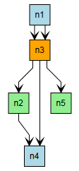
// edges should start at the right side at blue nodes and at the left side at green nodes
sourcePortConstraints: (edge) =>
edge.sourceNode.tag === 'blue'
? PortConstraint.create(PortSide.EAST)
: edge.sourceNode.tag === 'green'
? PortConstraint.create(PortSide.WEST)
: null,
targetPortConstraints: (edge) =>
edge.targetNode.tag === 'blue'
? PortConstraint.create(PortSide.WEST)
: edge.targetNode.tag === 'green'
? PortConstraint.create(PortSide.EAST)
: null
})
// and perform a layout
const layout = new HierarchicLayout()
graph.applyLayout(layout, layoutData)
}function performLayoutWithPortConstraints(graph: IGraph): void {
// use LayoutData to apply the source and target port constraints
const layoutData = new HierarchicLayoutData({
// edges should start at the right side at blue nodes and at the left side at green nodes
sourcePortConstraints: (edge) =>
edge.sourceNode!.tag === 'blue'
? PortConstraint.create(PortSide.EAST)
: edge.sourceNode!.tag === 'green'
? PortConstraint.create(PortSide.WEST)
: null,
targetPortConstraints: (edge) =>
edge.targetNode!.tag === 'blue'
? PortConstraint.create(PortSide.WEST)
: edge.targetNode!.tag === 'green'
? PortConstraint.create(PortSide.EAST)
: null
})
// and perform a layout
const layout = new HierarchicLayout()
graph.applyLayout(layout, layoutData)
}
The Logic Gates demo application shows in detail how to use PortConstraint with the HierarchicLayout.
Restricting Ports for Layout Algorithms which Do Not Support Port Constraints
Some layout algorithms do not support strong port candidates. However, one might still want to keep the ports in a fixed location, e.g. by enabling fixPorts. For such cases a FixPortLocationStage can be prepended.
// organic layout does not support port constraints
const coreLayout = new OrganicLayout({ preferredEdgeLength: 100 })

// We want to keep the ports at their current location, though
// Therefore, we prepend the FixPortLocationStage
// which applies PortConstraints after the actual layout
const layout = new FixPortLocationStage({
  coreLayout: coreLayout,
  keepCalculatedPorts: false
})

// enable FixPorts which internally adds
// strong port constraints at the current location
const ex = new LayoutExecutor({
  graphComponent: graphComponent,
  layout: layout,
  fixPorts: true
})
await ex.start()

// organic layout does not support port constraints
const coreLayout = new OrganicLayout({ preferredEdgeLength: 100 })

// We want to keep the ports at their current location, though
// Therefore, we prepend the FixPortLocationStage
// which applies PortConstraints after the actual layout
const layout = new FixPortLocationStage({ coreLayout: coreLayout, keepCalculatedPorts: false })

// enable FixPorts which internally adds
// strong port constraints at the current location
const ex = new LayoutExecutor({ graphComponent: graphComponent, layout: layout, fixPorts: true })
await ex.start()
In this example the port constraints are created automatically with fixPorts enabled. Individual port constraints can be applied, though, using FixPortLocationStageData's properties sourcePortConstraints and targetPortConstraints.
const layout = new FixPortLocationStage(
  new OrganicLayout({
    preferredEdgeLength: 100
  })
)
layout.keepCalculatedPorts = false

// create port constraints only for nodes which are no circles
const data = new FixPortLocationStageData({
  sourcePortConstraints: (edge) =>
    edge.sourceNode.style instanceof ShapeNodeStyle &&
    edge.sourceNode.style.shape !== ShapeNodeShape.ELLIPSE
      ? PortConstraint.create(PortSide.ANY, true)
      : null
})

await graphComponent.morphLayout(layout, '0.3s', data)

const layout = new FixPortLocationStage(
  new OrganicLayout({
    preferredEdgeLength: 100
  })
)
layout.keepCalculatedPorts = false

// create port constraints only for nodes which are no circles
const data = new FixPortLocationStageData({
  sourcePortConstraints: (edge) =>
    edge.sourceNode!.style instanceof ShapeNodeStyle && edge.sourceNode!.style.shape !== ShapeNodeShape.ELLIPSE
      ? PortConstraint.create(PortSide.ANY, true)
      : null
})

await graphComponent.morphLayout(layout, '0.3s', data)
Note that, technically, the ports are moved after the actual layout algorithm has finished. This might
result in strange edge paths, especially if there are bends. In such cases it might help to set
keepCalculatedPorts to true (the default). With this setting enabled
a bend is inserted at the location where the layout algorithm places the port while the actual port is kept at its
original location. For straight edge paths, however, it is better to set keepCalculatedPorts
to false. In this mode the port location itself is set to the original location.
keepCalculatedPorts should be set depending on the layout algorithm.
Usually algorithms which produce straight edges (like organic layout) should be used
with keepCalculatedPorts set to false.