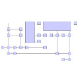
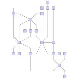
Orthogonal Layouts
Class OrthogonalLayout is a multi-purpose layout provider for undirected graphs. It produces clear representations of complex networks and is especially fit for application areas such as
- Software engineering
- Database schema
- System management
- Knowledge representation
The orthogonal layout algorithm is based on the topology-shape-metrics approach and consists of three phases. In the first phase the edge crossings in the drawing are calculated. The second phase computes the bends in the drawing, in the third phase the final coordinates are determined.
The layout algorithm is well suited for medium-sized sparse graphs. It produces compact drawings with no overlaps, few crossings, and few bends.
Basic Options
The global layout style of OrthogonalLayout is set using the layoutStyle property. Available options are:
- NORMAL
- Node sizes will not be changed by this layout algorithm. The drawing will contain very few bends only.
- UNIFORM
- All node sizes will be changed to equal size before the graph is processed.
- BOX
- Nodes are resized according to the number and position of their neighbors to reduce the overall number of bends.
- MIXED
- Resembles BOX, but resizes all nodes to equal size. Introduces additional bends and routes the last edge segment of these edges non-orthogonally to their adjacent nodes.
- FIXED_MIXED
- Proceeds similar to MIXED, but maintains original node sizes.
- FIXED_BOX
- Proceeds similar to BOX, but maintains original node sizes.
The layout style settings will be ignored for grouped graphs and directed orthogonal layout. Orthogonal layouts with one of these features enabled always use NORMAL.
- Grid
- gridSpacing
- Defines the virtual grid spacing used by the layout algorithm. Each node will be placed in such a way that its center point lies on a grid point. Edges will be routed in such a way that their segments lie on grid lines, if the terminal nodes of the edges allow to place the ports accordingly. Note that this option is only guaranteed to be obeyed for LayoutStyle.NORMAL, for all other styles it is used as a hint only.
- Length Reduction
- edgeLengthReduction
- If enabled, the overall edge lengths will be reduced, often making layouts significantly more compact. The cost for the reduction is an increased execution time of the layout algorithm.
- Optimize Perceived Bends
- optimizePerceivedBends
- If enabled, avoids helical arrangement of chains of nodes.
- Crossing Postprocessing
- crossingReduction
- If enabled, the overall number of edge crossings will be reduced. The cost for the reduction is increased execution time of the layout algorithm (especially when the graph has many edge crossings).
- Use Randomization
- randomization
- If enabled, the overall layout quality will increase with high probability. The cost for this layout optimization is increased execution time and non-deterministic results for subsequent layout invocations.
- Uniform Port Assignment
- uniformPortAssignment
- If enabled, the algorithm may insert additional bends in order to obtain a more uniform port assignment of edges incident to the same node side.
- Maximum Duration
- maximumDuration
- Specifies the preferred time limit in milliseconds. This setting is useful to restrict the running time of orthogonal layout. If there is a time limit, the algorithm may automatically disable some of the optimization settings mentioned above. Restricting the running time may result in a lower layout quality. Furthermore, the real runtime may exceed the specified maximum duration since the layout algorithm still has to find a valid solution.
- Use Existing Drawing as Sketch
- fromSketchMode
- If enabled, the layout algorithm interprets the initial graph layout as a sketch for the desired outcome of the layout process. The layout algorithm will try to orthogonalize the given sketch without making too many modifications with respect to the original drawing.
Class EdgeLayoutDescriptor can be used to specify further edge-related layout options. An instance of this class is held by OrthogonalLayout to store and retrieve default values for edges.
OrthogonalLayout provides access to the default EdgeLayoutDescriptor instance through:
- Edge Layout Descriptor
- edgeLayoutDescriptor
- Edge-related layout options.
In addition to the instance held directly by OrthogonalLayout, layout descriptors can also be associated with single edges in order to specify individual settings for them. Setting individual descriptors for edges is done through layout data. See Related Classes.
OrthogonalLayout by default also supports node halos as soon as they are declared using layout data. Furthermore, it is possible to define individual crossing costs and bend costs for each edge, which allows to treat some edges as more important than others. These costs are define via the according layout data properties, see crossing costs and bend costs.
Labeling
Integrated labeling is available for edge labels and can be used in conjunction with LayoutStyle.NORMAL. They are taken into consideration when determining both node placement and edge path generation. With this strategy it is guaranteed that no edge label will overlap other objects in the diagram.
Integrated labeling can be enabled or disabled using the following property:
- integratedEdgeLabeling
- Determines whether integrated labeling is enabled.
See also Integrated Labeling.
Optimal label placement with integrated labeling can be achieved using FreeEdgeLabelModel as the label model for the edges. As explained in Label Models, this edge label model is ideally suited in combination with integrated labeling and yields the best match for a label location that is computed by OrthogonalLayout.
OrthogonalLayout provides support for node label-aware orthogonal layout. Node labels do not need to be placed, but instead their size needs to be considered for the placement of adjacent graph elements. Taking node labels into consideration during layout calculation guarantees that they will not overlap nodes in the diagram.
- Consider Node Labels
- considerNodeLabels
- Enables node label-aware layout calculation.
Grouped Graphs
The OrthogonalLayout directly supports layout of grouped graphs. Both position and dimension of group nodes will be calculated by the algorithm.
Those parts of a graph that belong to the same group will be placed in a way that they share a common rectangular area in the layout space. The positions and sizes of these group nodes will be calculated by the algorithm.
The layout algorithm is well suited for medium-sized sparse graphs. It produces compact drawings with no overlaps, few crossings, and few bends.
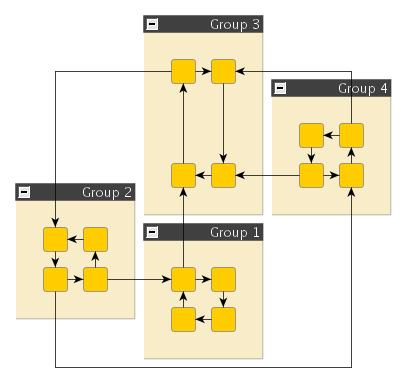
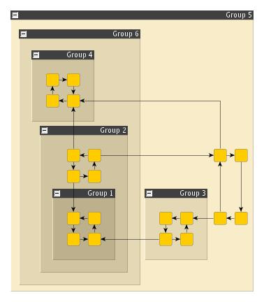
Setup of a grouped graph’s hierarchy of nodes (using GROUP_DP_KEY, NODE_ID_DP_KEY, PARENT_NODE_ID_DP_KEY, GROUP_NODE_INSETS_DP_KEY, and MINIMUM_NODE_SIZE_DP_KEY) is done transparently by the IGraph-related adapter mechanisms. See also Layout of Grouped Graphs and Applying an Automatic Layout.
Some features like directed edges, substructures and the from-sketch mode (see Basic Options) are not available in conjunction with grouped graphs.
Substructure Support
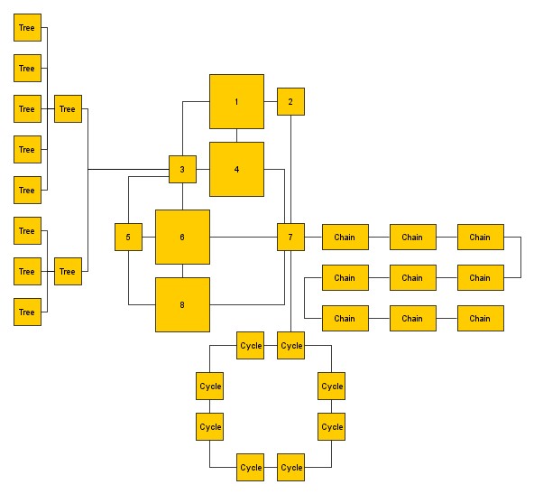
OrthogonalLayout is able to process several graph substructures in a specific way. The goal of this feature is to explicitly emphasize a certain structure by arranging it in an optimized fashion. Emphasizing such substructures can significantly improve the readability and clarity of orthogonal layouts. The user can choose among multiple styles for each type of substructure. Concretely, there is support for tree, chain and cycle structures available.
Settings related to substructures and their styles are available directly on the OrthogonalLayout instance.
The substructure feature works in conjunction with directed edges but is disabled if the graph is grouped. As soon as a data provider is registered under the key GROUP_DP_KEY, the graph is considered grouped. This is the case for grouped graphs if the IGraph-related adapter mechanisms are used. See also Layout of Grouped Graphs and Applying an Automatic Layout.
Substructures - Node Types
It is possible to define node types for the detection of substructures via the layout data property nodeTypes. A substructure can only contain nodes of the same type.
Substructures - Edge Directedness
It is possible to define the directedness of an edge for the detection of substructures via the layout data property edgeDirectedness. It allows to specify the directedness as a floating point value that is interpreted as follows:
- 0: undirected edge
- 1: edge is directed from the source to the target node
- -1: edge is directed from the target to the source node (reverse directed)
The directedness feature enables more control about which structures the algorithm should handle explicitly. A substructure is only detected as such if all edges are either undirected or consistently directed with respect to the direction value. If no custom directedness is specified, an edge is considered to be undirected.
The edge directedness must not be confused with the Directed Edge Drawings feature. The directedness value is solely used in conjunction with the detection of substructures.
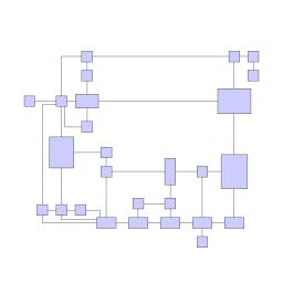
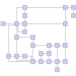
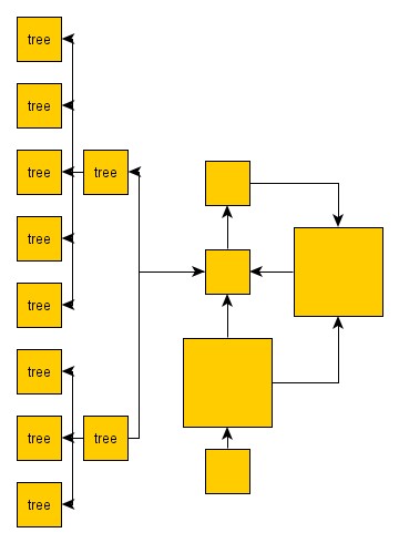
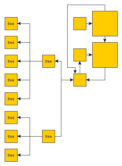
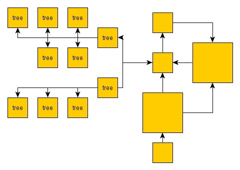
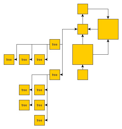
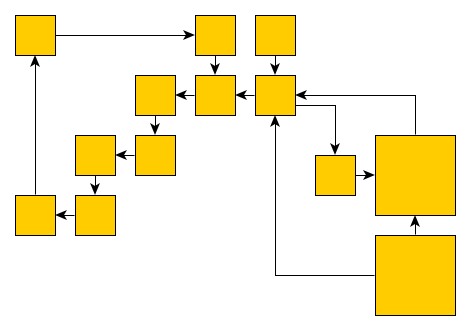
Tree Substructures
Tree substructure
The available styles for tree substructures are shown in the following figures. The style is configured by using property treeStyle.
Other settings with respect to tree substructures are (see API documentation for more details):
The general style of the two tree layout styles DEFAULT and INTEGRATED is quite similar. The difference lies in the internal approach. For the default style, a dedicated tree layout algorithm is applied to the tree structure and the computed layout is inserted into the orthogonal layout of the rest of the graph. In contrast, the integrated approach models the tree style internally, using the orthogonal layout framework. The integrated style can in consequence lead to results where the overall layout is more homogeneous and the grid is perfectly considered, whereas the generic approach might yield more compact layouts where trees are easily recognizable due to the highly different arrangement style.
Chain Substructures
The supported chain layout styles are depicted in the following figures. The style can be configured using property chainStyle.
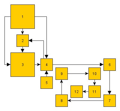
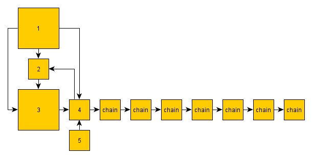
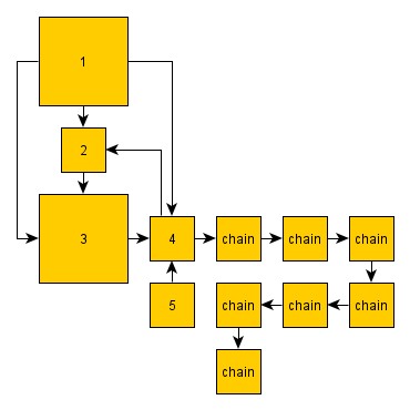
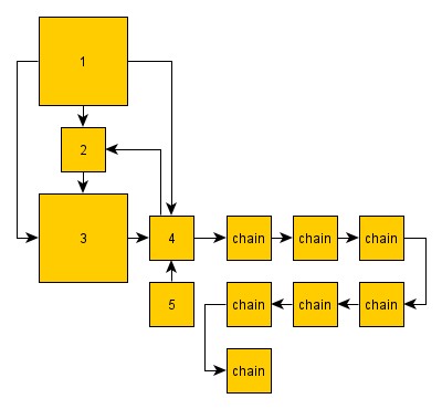
Additionally, it is possible to define the minimum size (number of nodes) a chain needs to have in order to be explicitly handled as a substructure by using property chainSize.
Cycle Substructures
The supported layout styles for cycle substructures are shown in the following figures. The style is specified by using property cycleStyle.
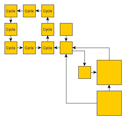
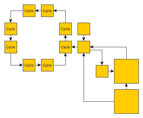
It is also possible to define the minimum size (number of nodes) a cycle needs to have in order to be explicitly handled as a substructure by using property cycleSize.
Applicable Layout Stages
Layout Stages lists layout stages that can be used to enhance the layout process of class OrthogonalLayout.
Layout Data
When using class OrthogonalLayout, supplemental layout data for a graph’s elements can be specified either by using class OrthogonalLayoutData or by registering data providers with the graph using given look-up keys. Supplemental layout data lists all properties of OrthogonalLayoutData and the corresponding look-up keys that OrthogonalLayout tests during the layout process in order to query supplemental data.
Providing supplemental layout data is described in detail in Layout Data.
Supplemental layout data
- GROUP_DP_KEY
- For each node a boolean value indicating whether it is a group node or not.Data Provider Key: GROUP_DP_KEYMaps from node to boolean
- NODE_ID_DP_KEY
- For each node an Object that serves as a unique ID.Data Provider Key: NODE_ID_DP_KEYMaps from node to Object
- PARENT_NODE_ID_DP_KEY
- For each node an Object indicating the group node it belongs to. The Object matches the unique ID of a group node that is in the same graph.Data Provider Key: PARENT_NODE_ID_DP_KEYMaps from node to Object
- GROUP_NODE_INSETS_DP_KEY
- For each group node an Insets object that encodes the group node’s insets.Data Provider Key: GROUP_NODE_INSETS_DP_KEYMaps from Node to Insets
- MINIMUM_NODE_SIZE_DP_KEY
- For each group node a YDimension object that specifies the group node’s minimum size constraint.Data Provider Key: MINIMUM_NODE_SIZE_DP_KEYMaps from node to YDimension
- EDGE_LABEL_LAYOUT_DP_KEY
- For each edge an array of LabelLayoutData objects that encode size and preferred placement for all labels of the edge.Data Provider Key: EDGE_LABEL_LAYOUT_DP_KEYMaps from edge to LabelLayoutData[]
- EDGE_LAYOUT_DESCRIPTOR_DP_KEY
- For each edge an EdgeLayoutDescriptor object that configures edge-related options.Data Provider Key: EDGE_LAYOUT_DESCRIPTOR_DP_KEYMaps from edge to EdgeLayoutDescriptor
directedEdges - For each edge a boolean value indicating whether it should be routed having main layout direction. See also Directed Edge Drawings.Data Provider Key: DIRECTED_EDGE_DP_KEYMaps from edge to boolean
edgeDirectedness - For each edge a floating point value that indicates the directedness of the edge, used for the detection of substructures. A value of zero means undirected, a positive value means directed and a negative value means reverse directed.Data Provider Key: EDGE_DIRECTEDNESS_DP_KEYMaps from edge to double
sourceGroupIds - For each edge an arbitrary Object indicating the group its source end is affiliated with. Edge grouping is only supported in conjunction with directed edges.Data Provider Key: SOURCE_GROUP_ID_DP_KEYMaps from edge to Object
targetGroupIds - For each edge an arbitrary Object indicating the group its target end is affiliated with. Edge grouping is only supported in conjunction with directed edges.Data Provider Key: TARGET_GROUP_ID_DP_KEYMaps from edge to Object
nodeHalos - A NodeHalo object that specifies the halo sizes at each side of a node.Data Provider Key: NODE_HALO_DP_KEYMaps from node to NodeHalo
edgeCrossingCosts - For each edge a positive floating point value defining the cost for crossing the edge or zero if crossing the edge should not be punished during the crossing minimization phase.Data Provider Key: EDGE_CROSSING_COST_DP_KEYMaps from edge to double
edgeBendCosts - For each edge a positive floating point value defining the cost for a bend of the edge or zero if bends of this edge should not be punished by the bend minimization.Data Provider Key: EDGE_BEND_COST_DP_KEYMaps from edge to double
abortHandler - An AbortHandler instance that will be queried by the layout algorithm to determine whether layout calculation shall be terminated.Data Provider Key: ABORT_HANDLER_DP_KEYMaps from graph to AbortHandler
- nodeTypes
- For each node an arbitrary Object indicating the node’s type, see Layout with Custom Node Types for more details.Data Provider Key: NODE_TYPE_DP_KEYMaps from node to Object
Directed Edge Drawings
The OrthogonalLayout optionally supports directed edge drawings (although not in combination with hierarchically nested graphs or the non-default layout styles). Application domains of directed orthogonal drawings include, for example, software engineering, database schema and system management.
It supports advanced edge path generation
- with respect to the so-called main layout direction, a predefined orientation, like, e.g., bottom-to-top, and also
- using a common anchor point and common edge segments for edges that connect to a common node.
The latter is also referred to as edge/port grouping, which is described in Layout with Edge Grouping.
Together these features enable high-quality graph layout which is a perfect match for UML-style class diagrams, for example. The layout algorithm is well suited for medium-sized graphs where a subset of edges should be routed with respect to the main layout direction. It produces compact drawings with no overlaps and few crossings.
This feature is not available with a grouped graph. As soon as a data provider is registered under the key GROUP_DP_KEY this feature will be disabled. This is the case for grouped graphs if the IGraph-related adapter mechanisms are used. See also Layout of Grouped Graphs and Applying an Automatic Layout.
Directed Edges
You can specify a subset of so-called directed edges that should be routed with respect to the main layout direction by means of layout data.
The main layout direction can be configured using the services of class OrientationLayout as outlined in Configuring the main layout direction Note that the default layout direction is top-to-bottom.
const orthogonal = new OrthogonalLayout()

// Set the main layout direction using the OrientationLayout provided by
// MultiStageLayout (the superclass of OrthogonalLayout).
const ol = orthogonal.orientationLayout
ol.orientation = LayoutOrientation.LEFT_TO_RIGHT

// Invoke the layout.
graph.applyLayout(orthogonal)
const orthogonal = new OrthogonalLayout()

// Set the main layout direction using the OrientationLayout provided by
// MultiStageLayout (the superclass of OrthogonalLayout).
const ol = orthogonal.orientationLayout as OrientationLayout
ol.orientation = LayoutOrientation.LEFT_TO_RIGHT

// Invoke the layout.
graph.applyLayout(orthogonal)
Edge Grouping
A special feature of the directed orthogonal layout algorithm is its ability to group multiple ports (edge end points) together to be anchored at the same location. You can specify this for both source ports and target ports by means of layout data. The setup of edge groups is described in Layout with Edge Grouping.
Compact Orthogonal Layout
Class CompactOrthogonalLayout is a specialized variant of the orthogonal layout algorithm. It uses a divide-and-conquer approach to achieve compact orthogonal layouts that fit into, respectively are near, a desired aspect ratio.
In contrast to the majority of yFiles layout algorithms, class CompactOrthogonalLayout does not inherit from MultiStageLayout, but is instead an extension of abstract class LayoutStageBase.
CompactOrthogonalLayout combines different phases that:
- find partitions in the node set of the graph
- calculate the orthogonal layout for the partitions
- arrange the partitions in a compact manner
- route the connecting edges between partitions
Basic Options
This specialized layout algorithm provides only few options by itself. However, the respective classes that are used for the different layout phases can be customized individually. In particular, this also includes the orthogonal layout algorithm which is used as the core layout algorithm.
- gridSpacing
- Defines the virtual grid spacing used by the layout algorithm. Each node is placed in such a way that its center point lies on a grid point.
- aspectRatio
- Specifies the desired aspect ratio that the resulting diagram should fit into. The algorithm tries to reach this value, depending on the actual graph structure, however, this may not always be feasible.
Applicable Layout Stages
Layout Stages lists layout stages that can be used to enhance the layout process of class CompactOrthogonalLayout.