Summary of Layout and Routing Styles
The layout algorithms of yFiles can be divided into three main categories:
- Layout styles are responsible for assigning locations to all graph elements. More precisely, the nodes of a graph are placed according to some optimization criteria, and edge paths are also generated (i.e., it is not required to apply an edge routing algorithm separately). Some algorithms also arrange labels in a way that there are no overlaps with each other or with graph elements.
- Edge routing styles process only edges, i.e., they compute edge paths. The nodes of a graph are left unchanged; neither their position nor their size is altered in any way. Hence, they are a good choice for use-cases where the node positions are already given or as a post-processing step for another layout algorithm.
- Label placement algorithms leave both a graph’s nodes and its edge paths unaltered, but compute suitable positions for labels. Their criteria for the arrangement are such that the labels do not overlap with each other or any of the graph elements.
In addition, some layout and edge routing styles provide support for specific visual and algorithmic features:
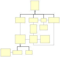
Hierarchical Layout
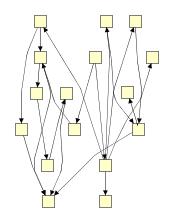
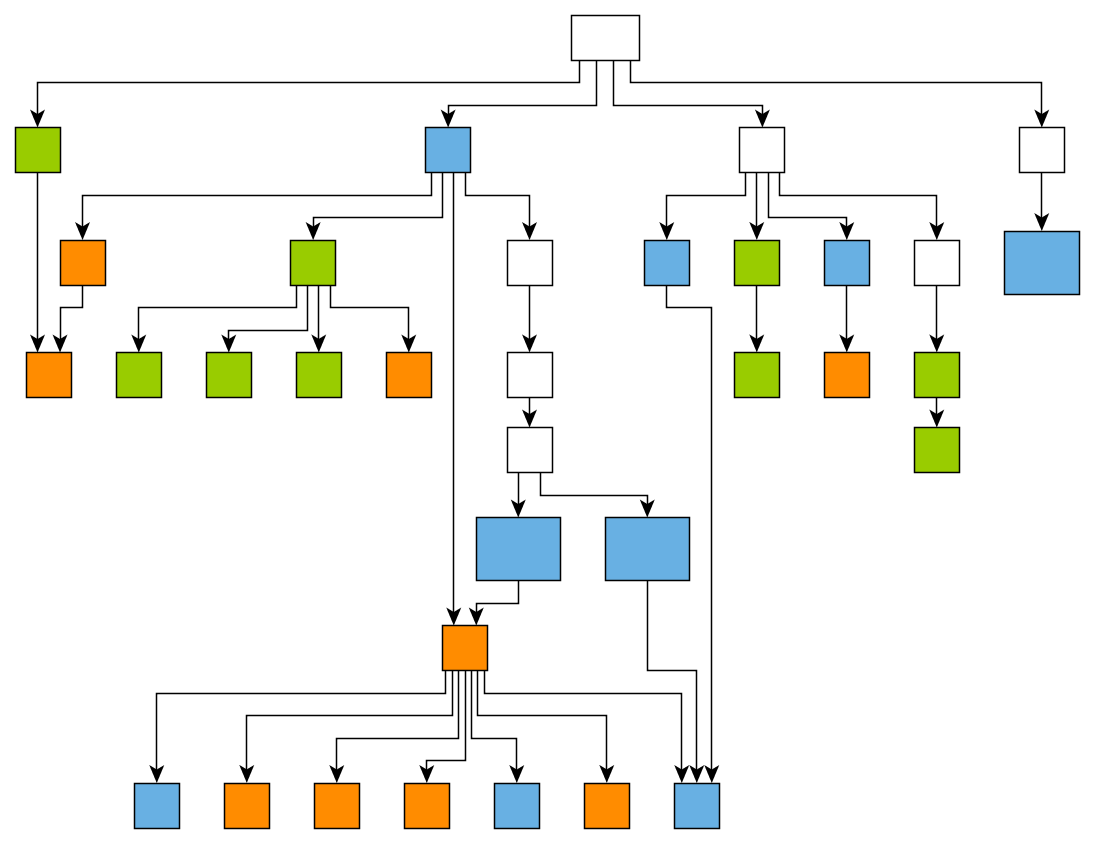
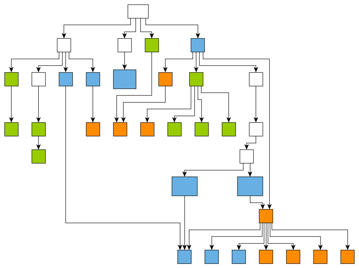
Hierarchical Layout arranges graphs in a hierarchic fashion. The nodes are distributed into layers so that most of the edges point to the main layout direction. The order of the nodes within the layers ensures that the number of edge crossings is as small as possible. There are different edge routing styles available. Edges can be orthogonal, polyline or octilinear.
Hierarchical diagrams are commonly used for the visualization of hierarchical data, since they facilitate the identification of dependencies and relationships among the nodes of the graph. Workflow visualization, call graph visualization, entity-relationship diagrams, biochemical pathways and network management are typical application domains for this type of layout.
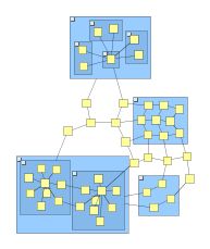
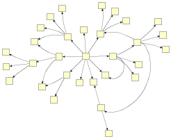
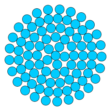
Organic Layout
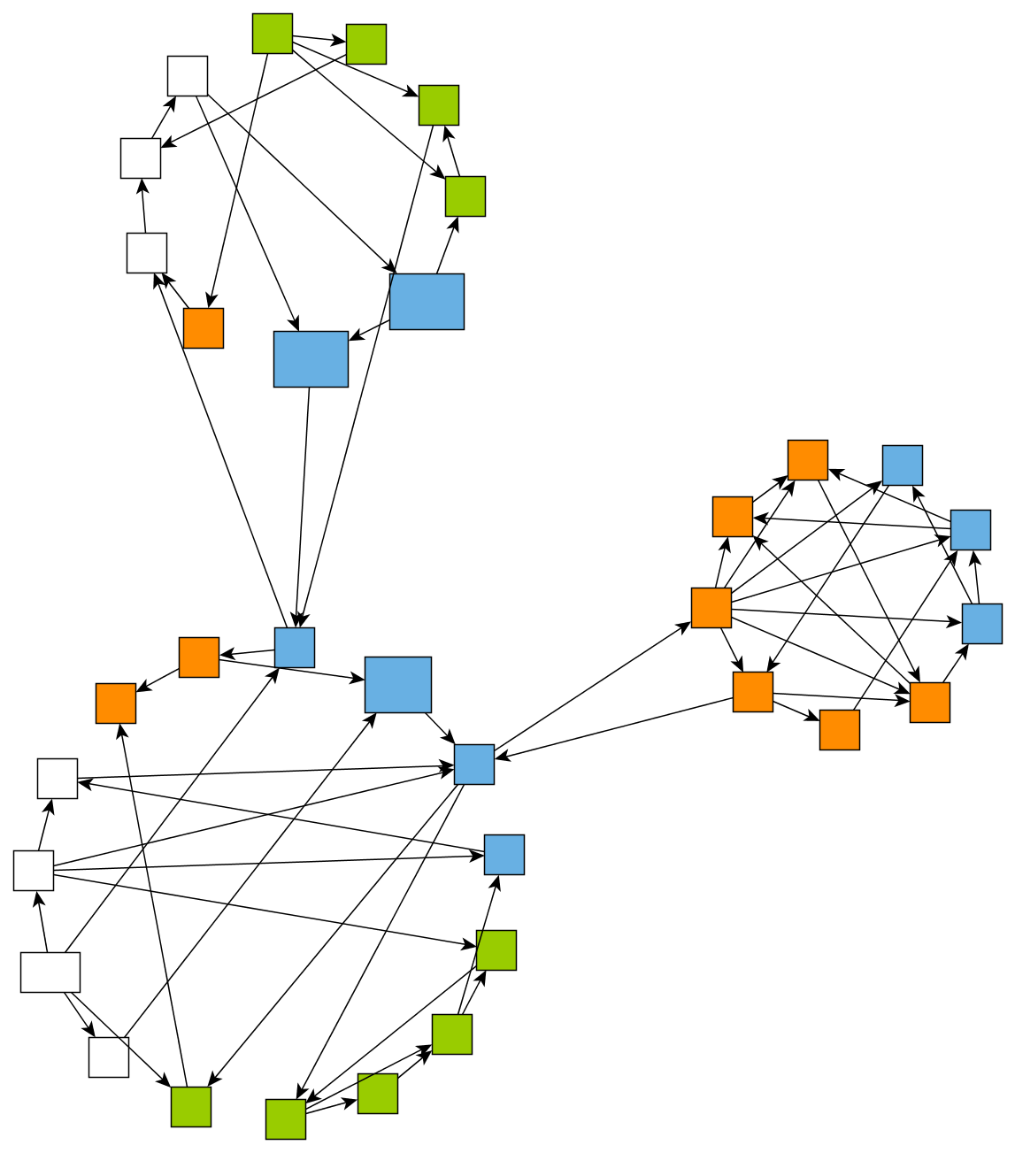
Organic Layouts are characterized by a natural distribution of nodes that exhibits clusters and symmetric properties of the graph. The layout is very compact, where nodes are placed close to their adjacent nodes. Edges maintain uniform lengths and are routed using straight-line segments without bends.
In addition to ClassicOrganicLayout for from scratch layouts, interactively changing and layouting a graph is also possible.
Organic diagrams are commonly used for visualizing relations in large networks, for example in bioinformatics, enterprise networking, visualizing social networks, mesh visualization or system management.
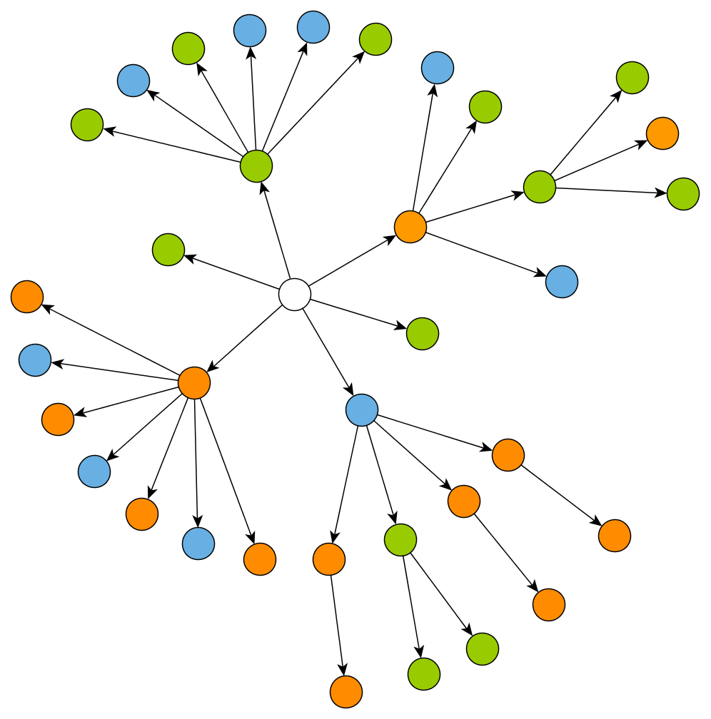
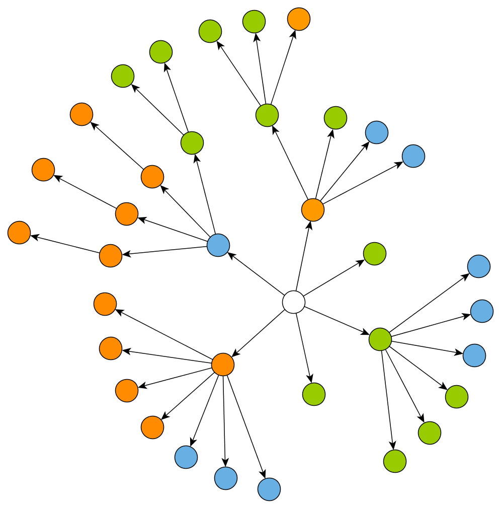
Tree Layout
Tree Layouts arrange graphs with a tree structure. yFiles provides a number of different tree layout styles:
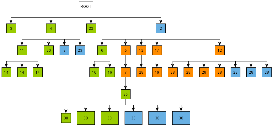
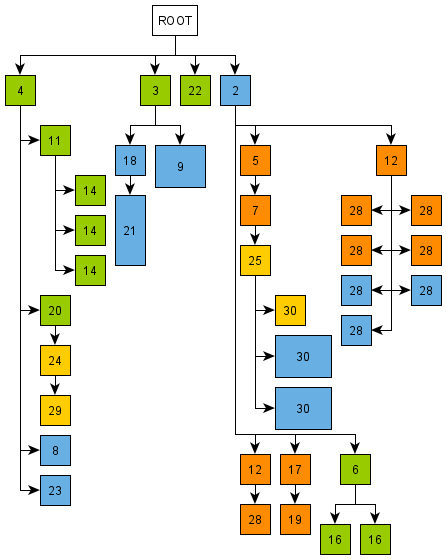
- The ClassicTreeLayout is designed to arrange directed and undirected trees that have a unique root node. All children are placed below their parent in relation to the main layout direction. The edges of the graph are routed as straight-line segments or in an orthogonal bus-like fashion.
- The TreeLayout provides multiple different arrangements of trees and subtrees. It is easy to customize the order of edges, the port assignment and the arrangement of the nodes for each subtree.
- The BalloonLayout places subtrees rooted at a node in a radial fashion around their root node. All direct children of one node can be placed on a common circle around their parent node (depending on the alignment policy). Therefore, subtrees look like balloons or stars, especially if subtrees have similar sizes. The edges of the tree are drawn as straight lines.
- The AspectRatioTreeLayout tries to generate compact tree layouts with a certain preferred aspect ratio.
Tree layout algorithms are commonly used for visualizing relational data and for producing diagrams that are able to reveal possible hierarchic properties of the graph. More precisely, they find applications in dataflow analysis, software engineering, bioinformatics and business administration.
Orthogonal Layout
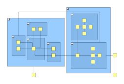
Orthogonal Layouts arrange the nodes of a given graph such that each edge is drawn as an alternating sequence of horizontal and vertical segments. It produces compact drawings with no overlapping nodes, few crossings and few bends and is well suited for small and medium-sized sparse graphs.
Application domains of orthogonal drawings include software engineering, database schema representation, system management, knowledge representation, VLSI circuits and floor planning applications.
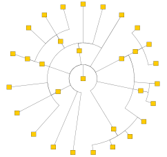
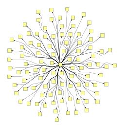
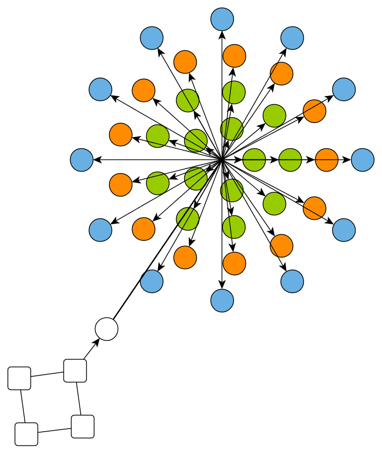
Circular Layout
Circular Layout is suitable to emphasize group and tree structures as well. In contrast to other tree layouts, the circular layout arranges the nodes in circles and stars.
Circular layout algorithms find applications in many areas such as social networking, network management, WWW visualization, e-commerce and telecommunications.
Radial Layout
Radial Layout distributes the nodes into circles (layers) around a common center based on predefined layering strategies.
Some potential applications include visualization of social networks, data clustering and bioinformatics.
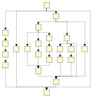
Series-parallel Layout
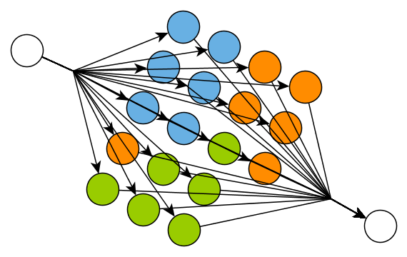
Series-parallel graphs are directed graphs with a single source (node without incoming edges) and a single sink (node without outgoing edges) that are built recursively by series and parallel compositions. Series-parallel Layout highlights the main layout direction (from source to sink). It also emphasizes the paths through the graph because edges are routed with few bends.
Series-parallel diagrams are suitable for the visualization of circuits, call trees or flowcharts.
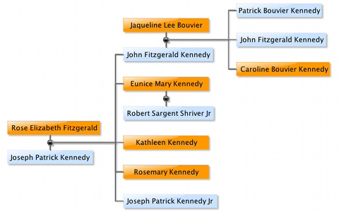
Family Tree Layout
Family Tree Layout arranges genealogical graphs (family trees). The family trees consist of nodes that represent individuals and nodes that represent families. Individuals are connected via these family nodes. The graph is arranged in layers that describe generations.
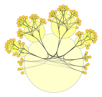
Cactus Group Layout
Cactus Group Layout is a layout algorithm for hierarchically grouped graphs that arranges all direct members of a group around its border, resulting in a recursive tree that resembles a cactus.
Compact Disk Layout
Compact Disk Layout is a layout algorithm that arranges the graph’s nodes on a disk optimizing the compactness of the placement.
Edge Routing Styles
All edge routing algorithms provided by yFiles implement the ILayoutStage interface. ILayoutStage makes it easy to use an edge routing algorithm as a postprocessing step to any of the major layout algorithm (e.g., first apply the organic layout to place the nodes and then an edge routing algorithm to obtain orthogonal instead of straight-line edge routes).
yFiles supports different edge routing styles:
Polyline Routing
Polyline Edge Routing can be applied wherever it is needed to route the edges as polyline or orthogonal segments without crossing any nodes, while keeping the positions of the nodes in the diagram fixed.
Some potential applications include electric circuit design, floor planning and navigation maps.
Channel Routing
Channel Edge Routing also generates orthogonal routes for the edges. Compared to the Polyline Routing, this implementation is usually faster but supports fewer constraints and, by default, may produce node-edge overlaps.
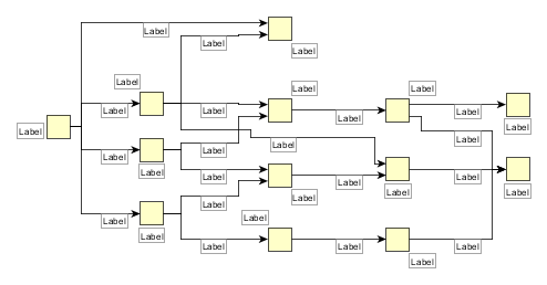
Bus Routing
Bus-style Edge Routing is a specialized edge routing algorithm that generates bus-style representations by bundling edges of complete (sub)graphs.
Organic Routing
Organic Edge Routing routes edges in smooth curves around the nodes.
Label Placement Algorithms
Generic Labeling is independent of any layout algorithm and can be applied to any kind of diagram. More precisely, it computes positions for labels in a given graph without modifying the positions of nodes or edges. Therefore it is a good starting point if you want to improve the labeling of your graph quickly. The main objective of the algorithm is to clarify the affiliations of the labels to their nodes or edges and at the same time avoid overlaps with other graph elements.
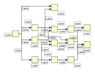
Integrated Labeling
Some layout algorithms already provide automatic edge label placement as an integrated part of the layout calculation. This way you can prevent label overlaps completely.
Layout of Grouped Graphs
As described in The Graph Model, yFiles for HTML provides an enhanced graph model with support for group nodes. In this model a node can be in another node, its parent group, and each group can contain an arbitrary number of nodes, its children.
A layout style that is suitable for group nodes typically places children of the same group near each other and have their parent enclosing them. The following layout and edge routing styles provide support for this kind of placement:
- Hierarchical Layout
- Organic Layout
- Orthogonal Layout
- Tree Layout
- Cactus Group Layout
- Series-parallel Layout
- Polyline Edge Routing
- Channel Edge Routing
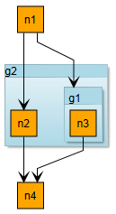
If an IGraph contains groups, applying a layout automatically creates a corresponding layout graph model with grouping information. Group node insets and minimum size constraints are automatically configured, too.
const graph = graphComponent.graph

// create some nodes
const n1 = graph.createNode()
const n2 = graph.createNode()
const n3 = graph.createNode()
const n4 = graph.createNode()

// and some group nodes
const g1 = graph.groupNodes([n3])
const g2 = graph.groupNodes([n2, g1])

// connect them with some edges
graph.createEdge(n1, n2)
graph.createEdge(n1, g1)
graph.createEdge(n2, n4)
graph.createEdge(n3, n4)

// and perform a layout
graph.applyLayout(new HierarchicLayout())
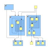
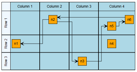
Layout of Tables and Swimlanes
Partitioned layouts, tabular layouts, and in particular the special case of swimlane layouts are supported by the PartitionGrid class.
This class specifies a grid that consists of rows and columns and the grid cells which result from the rows and columns. Each node can be assigned to a single partition cell or a set of consecutive partition cells and will stay in this cell(s) during layout. In addition to the structure, the class stores geometric information about rows and columns, for example minimum heights and widths, and insets.
The layout of a table shows a tabular layout. Note the partition into cells which results from the rows and columns.
The following layout and edge routing styles support tabular layouts:
- Hierarchical Layout
- Organic Layout
- Polyline Edge Routing
- Tabular Layout (only nodes, only a single node per cell)
Furthermore, the layout stage GenericPartitionGridStage offers generic support for partition grid structures. To configure the partition grid for the stage, use GenericPartitionGridStageData.
If an IGraph contains tables, applying a layout automatically creates a corresponding layout graph model with tabular information.Ultimately, this setup is done by the TableLayoutConfigurator class which creates a PartitionGrid of the Table. LayoutExecutor provides access to its TableLayoutConfigurator instance for advanced configuration and customization.
/**
 * @param {!GraphComponent} graphComponent
 * @param {!ITable} table
 * @returns {!Promise}
 */
async function populateAndLayoutTable(graphComponent, table) {
  const graph = graphComponent.graph

  // create a top-level group node and bind the table to it
  const parent = graph.createGroupNode(
    null,
    new Rect(0, 0, 10, 10),
    new TableNodeStyle(table)
  )

  // create some rows and columns
  const row1 = table.createRow()
  const row2 = table.createRow()
  const row3 = table.createRow()
  const column1 = table.createColumn()
  const column2 = table.createColumn()
  const column3 = table.createColumn()
  const column4 = table.createColumn()

  // populate some of the cells with nodes
  const n1 = createNodeInCell(graph, parent, row2, column1)
  const n2 = createNodeInCell(graph, parent, row1, column2)
  const n3 = createNodeInCell(graph, parent, row3, column3)
  const n4 = createNodeInCell(graph, parent, row2, column4)
  const n5 = createNodeInCell(graph, parent, row1, column4)
  const n6 = createNodeInCell(graph, parent, row1, column4)

  // connect them with some edges
  graph.createEdge(n2, n1)
  graph.createEdge(n2, n3)
  graph.createEdge(n3, n5)
  graph.createEdge(n5, n6)
  graph.createEdge(n6, n2)

  // and perform a layout
  const hierarchicLayout = new HierarchicLayout()
  hierarchicLayout.layoutOrientation = LayoutOrientation.LEFT_TO_RIGHT
  hierarchicLayout.orthogonalRouting = true
  await graphComponent.morphLayout({
    layout: hierarchicLayout,
    morphDuration: '1s'
  })

  // Create a node in the center of the given cell.
  function createNodeInCell(graph, parent, row, column) {
    const node = graph.createNode(parent)
    graph.setNodeCenter(
      node,
      new Point(column.layout.center.x, row.layout.center.y)
    )
    return node
  }
}async function populateAndLayoutTable(graphComponent: GraphComponent, table: ITable): Promise<void> {
  const graph = graphComponent.graph

  // create a top-level group node and bind the table to it
  const parent = graph.createGroupNode(null, new Rect(0, 0, 10, 10), new TableNodeStyle(table))

  // create some rows and columns
  const row1 = table.createRow()
  const row2 = table.createRow()
  const row3 = table.createRow()
  const column1 = table.createColumn()
  const column2 = table.createColumn()
  const column3 = table.createColumn()
  const column4 = table.createColumn()

  // populate some of the cells with nodes
  const n1 = createNodeInCell(graph, parent, row2, column1)
  const n2 = createNodeInCell(graph, parent, row1, column2)
  const n3 = createNodeInCell(graph, parent, row3, column3)
  const n4 = createNodeInCell(graph, parent, row2, column4)
  const n5 = createNodeInCell(graph, parent, row1, column4)
  const n6 = createNodeInCell(graph, parent, row1, column4)

  // connect them with some edges
  graph.createEdge(n2, n1)
  graph.createEdge(n2, n3)
  graph.createEdge(n3, n5)
  graph.createEdge(n5, n6)
  graph.createEdge(n6, n2)

  // and perform a layout
  const hierarchicLayout = new HierarchicLayout()
  hierarchicLayout.layoutOrientation = LayoutOrientation.LEFT_TO_RIGHT
  hierarchicLayout.orthogonalRouting = true
  await graphComponent.morphLayout({ layout: hierarchicLayout, morphDuration: '1s' })

  // Create a node in the center of the given cell.
  function createNodeInCell(graph: IGraph, parent: INode, row: IRow, column: IColumn): INode {
    const node = graph.createNode(parent)
    graph.setNodeCenter(node, new Point(column.layout.center.x, row.layout.center.y))
    return node
  }
}
The Table Editor demo application shows in detail how to create and automatically lay out tables.
Layout with Edge Grouping
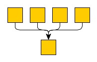
Edge grouping means that a set of edges is bundled at either their source or target end in the following way:
- Their source (or target) ports will be at the same location, if these ports belong to the same owner node.
- Their paths will share common segments, in other words, they are routed in a bus-like style.
If edges at different source (target) nodes are declared an edge group at their source (target) ends, then they will be routed in bus-style only. If edges from an edge group have associated inconsistent, or even contradicting port constraints, then the location of the common port is not guaranteed to obey any of them.
Edge grouping is sometimes called port grouping.
The following layout and edge routing styles provide support for edge grouping:
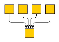
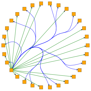
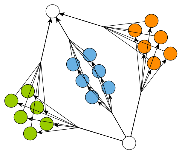
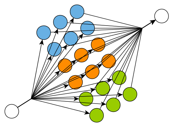
Declaring an edge group at the source or target ends of a set of edges is done by associating the same common object with these edges via the data provider keys SOURCE_GROUP_ID_DP_KEY or TARGET_GROUP_ID_DP_KEY, respectively.
Declaring an edge group for all edges targeting a given node demonstrates how an edge group for all edges targeting a given node is declared.
/**
 * @param {!IGraph} graph
 * @param {!INode} specificNode
 */
function performEdgeGrouping(graph, specificNode) {
  // specify an id for all edges ending in the particular node
  const targetEdgeGroupId = 'All my grouped edges.'

  // use LayoutData to configure the target edge groups
  const layoutData = new HierarchicLayoutData({
    targetGroupIds: (edge) =>
      edge.targetNode === specificNode ? targetEdgeGroupId : null
  })

  // and perform a layout
  graph.applyLayout(new HierarchicLayout(), layoutData)
}function performEdgeGrouping(graph: IGraph, specificNode: INode): void {
  // specify an id for all edges ending in the particular node
  const targetEdgeGroupId = 'All my grouped edges.'

  // use LayoutData to configure the target edge groups
  const layoutData = new HierarchicLayoutData({
    targetGroupIds: (edge: IEdge) => (edge.targetNode === specificNode ? targetEdgeGroupId : null)
  })

  // and perform a layout
  graph.applyLayout(new HierarchicLayout(), layoutData)
}
The Edge Grouping demo uses edge grouping to bundle incoming and outgoing edges.
Incremental Layout
The yFiles library provides unequaled support for incremental graph layout that seamlessly integrates with the “normal,” non-incremental major layout style.
Compared to a “normal” layout algorithm, which computes an all-new, fresh graph layout each time it is invoked, incremental layout rearranges distinct parts of a graph while the remainder is not, or only slightly, changed. This technique makes it possible to maintain the user’s mental map over a course of subsequent layouts of a changing graph, for example in interactive use cases where a user modifies a graph.
The term mental map expresses a user’s experience of a graph, which is most notably influenced by a consistent and largely invariable placement of the graph elements in a sequence of layout algorithm invocations. “Normal” layout calculation does not consider the mental map in any way. In fact, a graph layout may change substantially for modifications as small as adding a single edge!
The following layout and edge routing styles provide support for incremental layout:
- Hierarchical Layout
- Supports a dedicated incremental layout mode as well as hierarchical layout from scratch.
- Organic Layouts
- Incremental layout support is provided by means of the Scope feature.
- Tree Layout
- TreeLayout supports incremental layout by means of the default NodePlacer implementation. BalloonLayout can be set to layout from sketch mode. ClassicTreeLayout supports incremental layout by means of the default child comparer implementation.
- All edge routing styles
- Incremental routing support is provided by means of the Affected Edges feature. See the routing options of Organic Edge Routing, Polyline Edge Routing, Channel Edge Routing, and Bus-style Edge Routing for more information.
/**
 * @param {!IGraph} graph
 * @param {!Array.<Node>} nodesToLayout
 */
function performIncrementalLayout(graph, nodesToLayout) {
  // use LayoutData to configure the incremental nodes
  const layoutData = new HierarchicLayoutData({
    incrementalHints: {
      incrementalLayeringNodes: nodesToLayout
    }
  })

  // and perform an incremental layout
  const layout = new HierarchicLayout()
  layout.layoutMode = LayoutMode.INCREMENTAL
  graph.applyLayout(layout, layoutData)
}function performIncrementalLayout(graph: IGraph, nodesToLayout: Node[]): void {
  // use LayoutData to configure the incremental nodes
  const layoutData = new HierarchicLayoutData({
    incrementalHints: {
      incrementalLayeringNodes: nodesToLayout
    }
  })

  // and perform an incremental layout
  const layout = new HierarchicLayout()
  layout.layoutMode = LayoutMode.INCREMENTAL
  graph.applyLayout(layout, layoutData)
}
Use Cases
Incremental layout is closely related to layout from sketch, where a given arrangement of nodes is taken as the starting point for a layout calculation and also as a specification for the calculation’s desired outcome. Consequently, layout from sketch takes a major role in an incremental layout algorithm’s functionality.
Incremental layout has two major use cases, which both involve layout from sketch:
- Interactive creation of a graph structure where the layout calculation is performed dynamically with each newly inserted graph element.
- Subsequent improvement of distinct parts from an already existing graph layout, where the remainder of the layout stays mainly unchanged.
Related Concept
Partial layout is a related concept that also allows to layout distinct parts of a diagram. It allows to use completely different layout styles for certain parts of a diagram and add the results to the original, unaltered remainder of the layout. Layout algorithms that provide support for incremental layout, however, will often yield a more sound and truly integrated overall layout of a diagram.
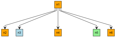
Node Padding (Halos)
A node halo specifies additional padding around a node. A layout algorithm that supports node halos keeps this area clear of graph elements, except the labels of this specific node and the incident segments of its edges. Class NodeHalo can be used to denote a node’s additional size requirements.
The following layout and edge routing styles provide support for node halos:
- Hierarchical Layout
- Organic Layout
- Tree Layout
- Balloon Layout
- Classic Tree Layout
- Orthogonal Layouts
- Circular Layout
- Radial Layout
- Cactus Group Layout
- Component Layout
- Polyline Edge Routing
Node halos are also supported by the following labeling algorithms and layout stages:
Declaring additional size requirements for a node is done by associating a corresponding NodeHalo object with the node via layout data or the data provider key NODE_HALO_DP_KEY. All layout and edge routing styles that support node halos respect the additional size requirement of each node with associated NodeHalo object without further configuration.
/**
* @param {!IGraph} graph
*/
function performLayoutWithHalos(graph) {
// specify an halo with extra space on the left side
const leftHalo = NodeHalo.create(0, 100, 0, 0)
// and another with extra space on the right side
const rightHalo = NodeHalo.create(0, 0, 0, 100)
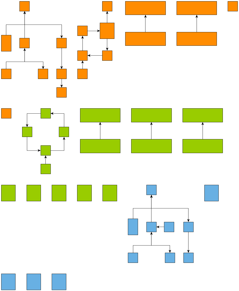
// blue nodes should have extra space at the right side and green ones on the left side
// use LayoutData to apply the halos
const layoutData = new HierarchicLayoutData({
nodeHalos: (node) =>
node.tag === 'blue' ? rightHalo : node.tag === 'green' ? leftHalo : null
})
// and perform a layout
const layout = new HierarchicLayout()
graph.applyLayout(layout, layoutData)
}function performLayoutWithHalos(graph: IGraph): void {
// specify an halo with extra space on the left side
const leftHalo = NodeHalo.create(0, 100, 0, 0)
// and another with extra space on the right side
const rightHalo = NodeHalo.create(0, 0, 0, 100)
// blue nodes should have extra space at the right side and green ones on the left side
// use LayoutData to apply the halos
const layoutData = new HierarchicLayoutData({
nodeHalos: (node) => (node.tag === 'blue' ? rightHalo : node.tag === 'green' ? leftHalo : null)
})
// and perform a layout
const layout = new HierarchicLayout()
graph.applyLayout(layout, layoutData)
}
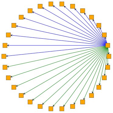
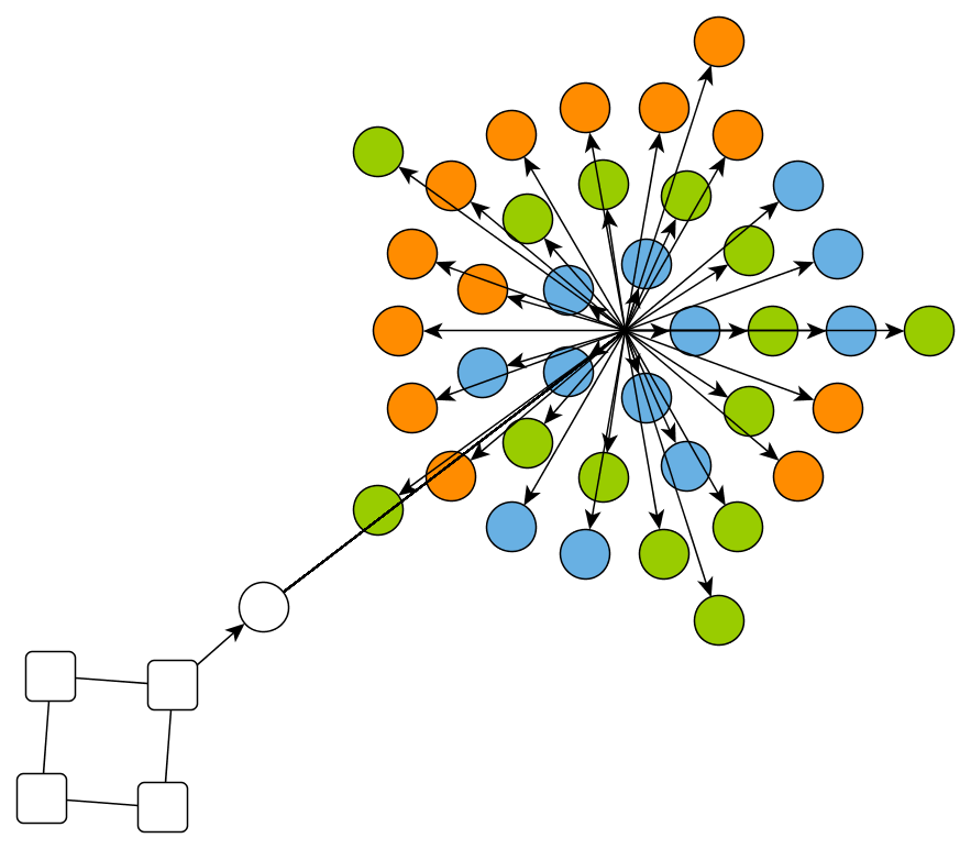
Edge Bundling
The edge bundling feature can be used to bundle the paths of edges in a diagram so that they follow similar routes.
Using edge bundling significantly reduces the visual clutter in drawings of large graphs with many edges. In addition, high-level patterns of edge routes and relations between different groups of nodes can be highlighted and easily recognized. Edge bundling is commonly used in bio-informatics, social network analysis, telecommunications, and in fraud detection.
Classes EdgeBundling and EdgeBundleDescriptor provide the means to configure options related to the edge bundling support.
The following layout algorithms provide support for edge bundling:
The EdgeBundlingStage is a generic stage that creates bundled paths based on the layout generated by any given core layout algorithm. Therefore, it can be applied when using an algorithm different from the ones mentioned above. Note that this stage ignores the current edge bends and may produce overlaps between nodes and edges.
/**
 * @param {!IGraph} graph
 */
function performLayoutWithEdgeBundles(graph) {
  // blue edges should be bundled
  const blueEdgeBundleDescriptor = new EdgeBundleDescriptor()
  blueEdgeBundleDescriptor.bundled = true
  // green edges should not be bundled
  const greenEdgeBundleDescriptor = new EdgeBundleDescriptor()
  greenEdgeBundleDescriptor.bundled = false

  // assign the edge bundle descriptors to the edges depending on their color
  // e.g. on the value stored in their tag
  // use LayoutData to apply the edge bundle descriptors
  const layoutData = new CircularLayoutData({
    edgeBundleDescriptors: (edge) =>
      edge.tag === 'blue'
        ? blueEdgeBundleDescriptor
        : edge.tag === 'green'
          ? greenEdgeBundleDescriptor
          : null
  })

  // and perform a layout
  const layout = new CircularLayout({
    partitionStyle: PartitionStyle.CYCLE,
    layoutStyle: CircularLayoutStyle.SINGLE_CYCLE
  })
  graph.applyLayout(layout, layoutData)
}function performLayoutWithEdgeBundles(graph: IGraph): void {
  // blue edges should be bundled
  const blueEdgeBundleDescriptor = new EdgeBundleDescriptor()
  blueEdgeBundleDescriptor.bundled = true
  // green edges should not be bundled
  const greenEdgeBundleDescriptor = new EdgeBundleDescriptor()
  greenEdgeBundleDescriptor.bundled = false

  // assign the edge bundle descriptors to the edges depending on their color
  // e.g. on the value stored in their tag
  // use LayoutData to apply the edge bundle descriptors
  const layoutData = new CircularLayoutData({
    edgeBundleDescriptors: (edge) =>
      edge.tag === 'blue' ? blueEdgeBundleDescriptor : edge.tag === 'green' ? greenEdgeBundleDescriptor : null
  })

  // and perform a layout
  const layout = new CircularLayout({
    partitionStyle: PartitionStyle.CYCLE,
    layoutStyle: CircularLayoutStyle.SINGLE_CYCLE
  })
  graph.applyLayout(layout, layoutData)
}
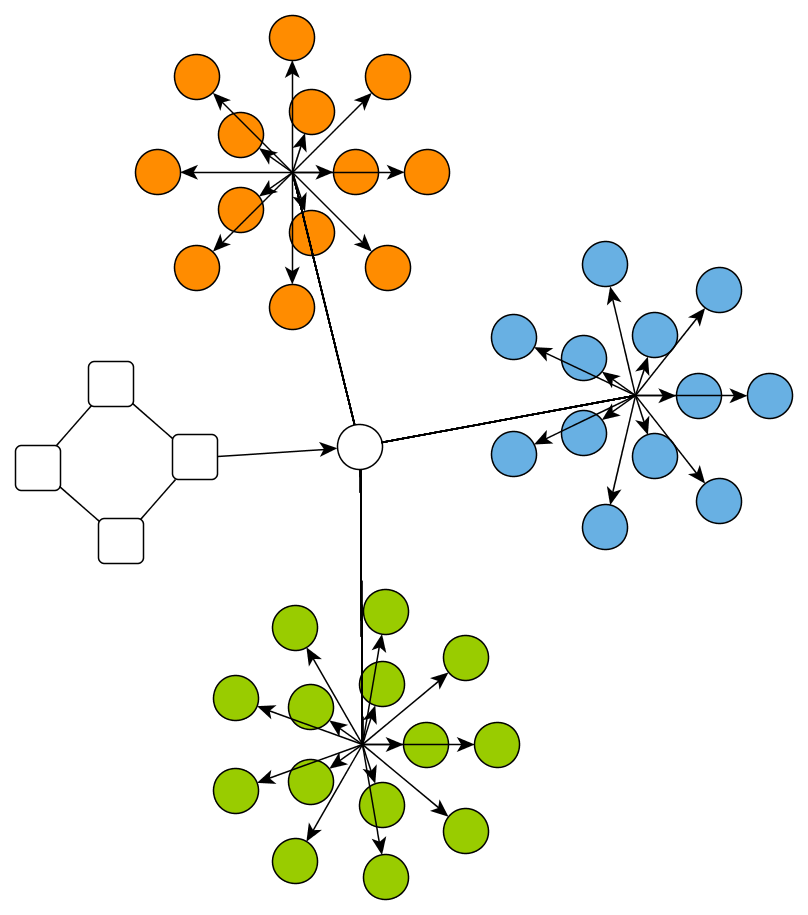
Layout with Custom Node Types
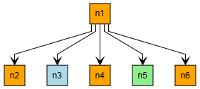
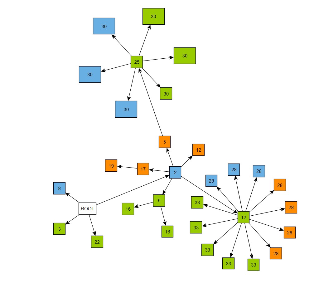
In many use-cases, node elements are associated with some specific types. There are several possibilities to highlight elements of different types, e.g., using a particular shape or color. To further emphasize types, nodes can be restricted accordingly during the layout calculation, e.g., by using group nodes or swimlanes to separate nodes of different types. These kinds of drawing constraints have a very significant impact on the result, which might not always be desirable. The more lightweight nodes types feature presents a solution for this. Algorithms that support it usually have some degrees of freedom for placing the nodes, which can be exploited to prefer placing nodes of the same type closer to each other without affecting the overall layout result too much.
Declaring node types is done by associating an arbitrary object with the nodes via layout data (see property NodeTypes), or the data provider key NODE_TYPE_DP_KEY. All layout algorithms that support node types assume that nodes associated with the same common object are of the same type.
The type is generally treated as a secondary, subordinate optimization criterion. Thus, nodes of the same type are usually not simply clustered together. The type is only considered when some free choice is available after considering other constraints relevant to the layout algorithm (like minimizing the number of crossings or considering the hierarchical grouping structure).
Layout support for node types lists the layout algorithms that provide support for node types. Defining node types has no effect on other layouts. In the following sections we describe in more detail how the various layouts handle node types.
| Layout Style | Class Name | Note |
|---|---|---|
Node Types in the Hierarchical Layout
The HierarchicLayout class uses the types of the nodes as a subordinate criterion during the sequencing of nodes within their layer. It prefers to place nodes of the same type next to each other if this does not induce additional crossings or conflicts with other constraints (like groups, swimlanes, or sequence constraints). The algorithm uses an additional local optimization heuristic to improve the placement with respect to node types and, thus, does not guarantee optimal results. Furthermore, this extra step may increase the required runtime. The node types do not affect the layer assignment in any way.
Node Types in the Organic Layout
In the OrganicLayout class, the node type affects the detection of substructures (e.g. star structures, cycles, chains). If types are defined, each substructure either consists of nodes that all have the same type or only of nodes without type. For parallel and star structures, the organic layout also offers to turn off this strict separation, with the effect that types are still considered, but only within a structure to, e.g., improve the ordering of nodes. See the properties parallelSubstructureTypeSeparation and starSubstructureTypeSeparation.
Node Types in the Orthogonal Layout
Similar to the organic layout, the OrthogonalLayout considers node types to strictly separate substructures. The types have no effect on the rest of the orthogonal layout algorithm.
Node Types in the Tree Layout
The TreeLayout and ClassicTreeLayout use the node types as a criterion, if there is no user-specified out-edge comparer. In such cases, the algorithm places siblings of the same type next to each other.
Note that some node placer implementations have placement criteria that are stronger than node types. For example, the CompactNodePlacer optimizes the compactness and this remains the main target even though types are defined. Hence, nodes of the same type might not be placed next to each other.
Node Types in the Circular Layout
To support node types in the CircularLayout, there is the custom node sequencer implementation NodeTypeAwareSequencer. It ensures that the nodes of a circle partition are sorted according to their type. The sequencer must be specified on the respective property nodeSequencer of the single cycle layout instance used by the CircularLayout (singleCycleLayout).
Node Types in the Component Layout
The ComponentLayout class takes types into consideration when arranging components. If all nodes of a component have the same type, the component is considered to be of that type. Components with same type are preferably put next to each other. The arrangement styles most suitable for node types are ROWS, SINGLE_ROW, SINGLE_COLUMN, and MULTI_ROWS_TYPE_SEPARATED.
The style MULTI_ROWS_TYPE_SEPARATED is specifically designed for usages with node types. It assures that each row contains only nodes of the same type. In other respects, the style uses the same strategy as MULTI_ROWS.
Node Types in the Balloon Layout
The BalloonLayout features sorting out-edges of a node according to the type of the edge’s target node. If node types are specified and no custom comparer supersedes the node types, all children of a node with equal types are consecutive around their parent node.
Node Types in the Radial Layout
The RadialLayout class uses the types of the nodes as a subordinate criterion for nodes of the same circle. More precisely, for nodes of the same circle (i.e., within the same layer), the algorithm prefers to place nodes of the same type next to each other if this does not induce additional crossings or conflicts with other constraints. Note that the algorithm uses an additional local optimization heuristic to improve the placement with respect to node types and, thus, does not guarantee optimal results. Furthermore, this additional step may increase the required runtime. The node types do not affect the layer assignment in any way.