| Rendering-related Features | ||
|---|---|---|
| Prev | Chapter 2. Displaying and Editing Graphs | Next |
Class BridgeManager![]() provides
support for inserting so-called bridges into edge paths.
Bridges are a means to resolve the visual ambiguity induced by intersecting
edge paths.
Each segment of an edge path that intersects with at least one other segment
(from either the same or another edge path), can be augmented with a bridge in
one of a variety of different styles.
provides
support for inserting so-called bridges into edge paths.
Bridges are a means to resolve the visual ambiguity induced by intersecting
edge paths.
Each segment of an edge path that intersects with at least one other segment
(from either the same or another edge path), can be augmented with a bridge in
one of a variety of different styles.
Table 2.16, “Some bridge rendering styles” presents some of the bridge styles supported by
BridgeManager. The STYLE constants of BridgeManager![]() are used to specify the styles.
are used to specify the styles.
Table 2.16. Some bridge rendering styles
| Name | Bridge Style |
|---|---|
| STYLE_GAP |
 |
| STYLE_ARC |
 |
| STYLE_RECTANGLE |
 |
| STYLE_TWO_SIDES |
 |
Example 2.28, “Using class BridgeManager with a GraphCanvasComponent” shows how to use a BridgeManager with default configuration to add bridges to the edge paths of a canvas's graph.
Example 2.28. Using class BridgeManager with a GraphCanvasComponent
function enableBridgesForEdgePaths(canvas:GraphCanvasComponent):void {
  var bridges:BridgeManager = new BridgeManager();
  bridges.canvasComponent = canvas;
  bridges.addObstacleProvider(new GraphObstacleProvider());
}
Class BridgeManager uses an implementation of interface
IObstacleProvider![]() to determine
"obstacles" that need to be taken into account during rendering.
The interface's single method is used to get a GeneralPath that defines an
actual obstacle.
to determine
"obstacles" that need to be taken into account during rendering.
The interface's single method is used to get a GeneralPath that defines an
actual obstacle.
By default, an appropriate implementation of IObstacleProvider![]() can be found in the lookup of each edge that uses a
PathBasedEdgeStyleRenderer-based style renderer.
can be found in the lookup of each edge that uses a
PathBasedEdgeStyleRenderer-based style renderer.
GraphObstacleProvider![]() , which
is used in the above example code, is a convenience implementation that by
default incorporates the obstacle definitions returned by all edges from the
current graph in the BridgeManager's CanvasComponent.
Optionally, using the
queryNodes
, which
is used in the above example code, is a convenience implementation that by
default incorporates the obstacle definitions returned by all edges from the
current graph in the BridgeManager's CanvasComponent.
Optionally, using the
queryNodes![]() property, obstacle definitions returned by all nodes can also be incorporated.
property, obstacle definitions returned by all nodes can also be incorporated.
Note that obstacles are not restricted to describe edge segments alone. In tutorial demo application BridgeDemo, for example, an IObstacleProvider implementation is presented that defines the border of group nodes as obstacles as well.
Class BridgeManager knows several policies for determining crossings between
obstacles.
BridgeManager![]() 's
DETERMINE constants are used to specify the determination policy.
For example, edge segments that have predominant horizontal orientation can be
chosen to always lie atop of edge segments having vertical orientation by setting
BridgeManager's crossingDetermination
's
DETERMINE constants are used to specify the determination policy.
For example, edge segments that have predominant horizontal orientation can be
chosen to always lie atop of edge segments having vertical orientation by setting
BridgeManager's crossingDetermination![]() to DETERMINE_MORE_HORIZONTAL_BRIDGES_LESS_HORIZONTAL.
to DETERMINE_MORE_HORIZONTAL_BRIDGES_LESS_HORIZONTAL.
Class GraphModelManager![]() provides
support to influence the z-order of visualizations of the graph model item.
The z-order (also called render order) determines, in what order graph model items are rendered. Items having a
lower z-order are rendered earlier and may be covered by items with a higher z-order.
The render order is primarily determined by the layers in the scene graph (see the section called “Scene Graph Addendum”)
and can be fine tuned by using z-order indices to adjust the order of items on the same layer.
In the section called “Layer Policies” different policies are illustrated that determine what layers for edges, labels and ports are used
while the section called “Z-Order Indices” describes how the z-order indices of items on the same layer can be manipulated by the
z-order support mechanism.
provides
support to influence the z-order of visualizations of the graph model item.
The z-order (also called render order) determines, in what order graph model items are rendered. Items having a
lower z-order are rendered earlier and may be covered by items with a higher z-order.
The render order is primarily determined by the layers in the scene graph (see the section called “Scene Graph Addendum”)
and can be fine tuned by using z-order indices to adjust the order of items on the same layer.
In the section called “Layer Policies” different policies are illustrated that determine what layers for edges, labels and ports are used
while the section called “Z-Order Indices” describes how the z-order indices of items on the same layer can be manipulated by the
z-order support mechanism.
The layering for nodes is determined by the node hierarchy. All nodes with the same parent are in its content layer.
Therefore if the graph hierarchy is flat, i.e. there are no group nodes, all nodes are in the same layer.
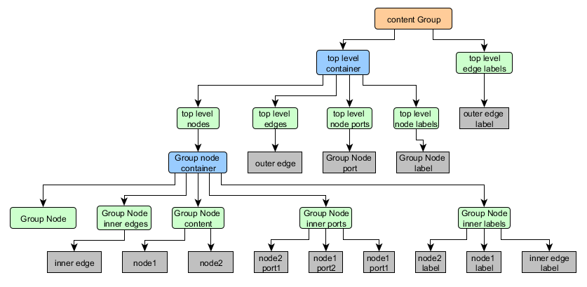
For edges, labels and ports, different layer policies can be set on the GraphModelManager![]() using the properties in Table 2.17, “Support for layer policies on GraphModelManager”.
The effects on the scene graph and the resulting visualization are depicted in the figures below.
using the properties in Table 2.17, “Support for layer policies on GraphModelManager”.
The effects on the scene graph and the resulting visualization are depicted in the figures below.
Table 2.17. Support for layer policies on GraphModelManager
| Property | Description |
|---|---|
| edgeLayerPolicy:EdgeLayerPolicy |
Sets the policy for edges as described in the section called “Edge Layer Policies”. |
| labelLayerPolicy:LabelLayerPolicy |
Sets the policy for labels as described in the section called “Port And Label Layer Policies”. |
| portLayerPolicy:PortLayerPolicy |
Sets the policy for ports as described in the section called “Port And Label Layer Policies”. |
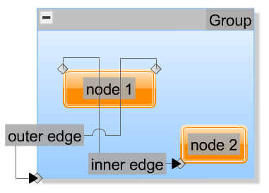
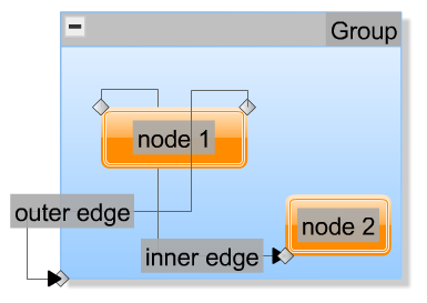
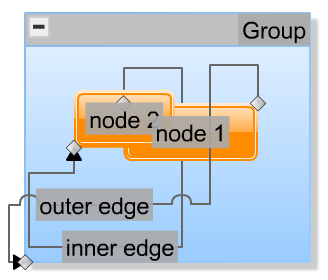
Figure 2.24, “An example graph visualized using the default layer policies” shows a small graph with two nodes in a group node that have
labels and ports and are visualized using the default policies, i.e. EdgeLayerPolicy.SEPARATE_LAYER![]() for edges, LabelLayerPolicy.AT_OWNER
for edges, LabelLayerPolicy.AT_OWNER![]() for labels and
PortLayerPolicy.AT_OWNER
for labels and
PortLayerPolicy.AT_OWNER![]() for ports:
for ports:
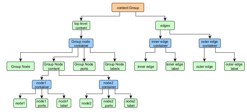
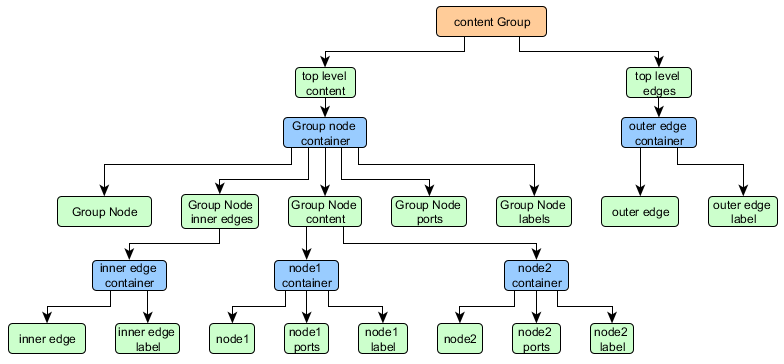
The corresponding scene graph section for this graph is depicted in Figure 2.25, “Scene graph section for the default layer policies”.
The default edge layer policy, SEPARATE_LAYER![]() , puts all
edges together in a separate edge layer that is on top of the node hierarchy. The scene graph and an example are
shown in the figures above.
, puts all
edges together in a separate edge layer that is on top of the node hierarchy. The scene graph and an example are
shown in the figures above.
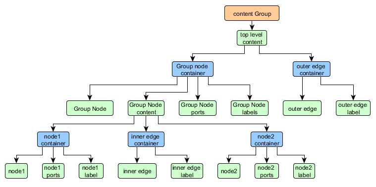
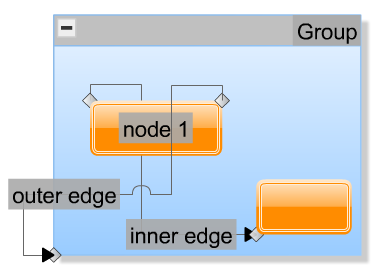
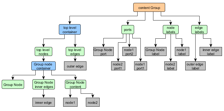
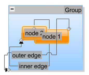
With the edge layer policy AT_NODE_LEVEL![]() ,
no separate edge layer is added for each node. Instead of this, an edge is put in the content layer of the common
ancestor node of its source and target node together with the child nodes of this ancestor.
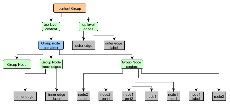
Figure 2.26, “Scene graph section for the edge layer policy AT_NODE_LEVEL” shows how this affects the scene graph:
,
no separate edge layer is added for each node. Instead of this, an edge is put in the content layer of the common
ancestor node of its source and target node together with the child nodes of this ancestor.
Figure 2.26, “Scene graph section for the edge layer policy AT_NODE_LEVEL” shows how this affects the scene graph:
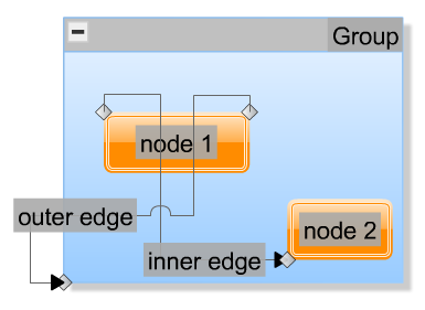
In the corresponding visualization you can notice, that the 'inner edge' now runs in front of 'node 1', but is still behind the port at 'node 2':
Using the third edge layer policy BEHIND_GROUP_NODES![]() ,
an edge layer is added for each node that contains the visualization of edges between child nodes this node is a common ancestor
of.
,
an edge layer is added for each node that contains the visualization of edges between child nodes this node is a common ancestor
of.
In the example graph above, 'inner edge' is an edge between 'node 1' and 'node 2'. As 'Group' is the common ancestor of these nodes, the visualization of 'inner edge' is put in the edge layer of 'Group'. 'outer edge' is an edge between 'node 1' and 'Group' and as 'Group' is top-level and has no ancestor, 'outer edge' is put in the top level edges layer.
Ports and labels use analogue policies. The default policies LabelLayerPolicy.AT_OWNER![]() respectively PortLayerPolicy.AT_OWNER
respectively PortLayerPolicy.AT_OWNER![]() create a label and port sub layer for each node that contain the canvas objects for the labels and ports of this node.
Figure 2.25, “Scene graph section for the default layer policies” depicts the scene graph of our example graph for this case.
create a label and port sub layer for each node that contain the canvas objects for the labels and ports of this node.
Figure 2.25, “Scene graph section for the default layer policies” depicts the scene graph of our example graph for this case.
The second policy type LabelLayerPolicy.AT_OWNER_LEVEL![]() respectively PortLayerPolicy.AT_OWNER_LEVEL
respectively PortLayerPolicy.AT_OWNER_LEVEL![]() has a similar effect as the edge layer policy AT_NODE_LEVEL
has a similar effect as the edge layer policy AT_NODE_LEVEL![]() :
it puts the canvas objects for labels and ports in the same layer as the node they belong to. This can lead to the effect
that
some of the labels and/or ports are rendered behind the node they belong to as shown in Figure 2.30, “Example graph for the port and label policy AT_OWNER_LEVEL”
:
it puts the canvas objects for labels and ports in the same layer as the node they belong to. This can lead to the effect
that
some of the labels and/or ports are rendered behind the node they belong to as shown in Figure 2.30, “Example graph for the port and label policy AT_OWNER_LEVEL”
These policies allow quite flexible z-ordering but should only be used in conjunction with z-order indices as described in the section called “Z-Order Indices”. The corresponding scene graph section is shown in Figure 2.31, “Scene graph section for the port and label policy AT_OWNER_LEVEL”.
The policy types LabelLayerPolicy.ON_TOP_OF_OWNER_LEVEL![]() and PortLayerPolicy.ON_TOP_OF_OWNER_LEVEL
and PortLayerPolicy.ON_TOP_OF_OWNER_LEVEL![]() put
the labels and ports a further level up in the scene graph so they are not put in a sub-layer of their owner, but in the
label and port sub-layer of the ancestor of their owner as depicted in Figure 2.32, “Scene graph section for the port and label policy ON_TOP_OF_OWNER_LEVEL”.
put
the labels and ports a further level up in the scene graph so they are not put in a sub-layer of their owner, but in the
label and port sub-layer of the ancestor of their owner as depicted in Figure 2.32, “Scene graph section for the port and label policy ON_TOP_OF_OWNER_LEVEL”.
Using these policies, all labels and ports of nodes, that have the same ancestor, are put in one layer that is on top of these nodes, so if the nodes are overlapping, the labels and ports are not hidden by these nodes as shown in Figure 2.33, “Nodes with a common ancestor don't hide each others' labels and ports using the policy ON_TOP_OF_OWNER_LEVEL”.
Figure 2.33. Nodes with a common ancestor don't hide each others' labels and ports using the policy ON_TOP_OF_OWNER_LEVEL
 |
By the LabelLayerPolicy.SEPARATE_LAYER![]() respectively PortLayerPolicy.SEPARATE_LAYER
respectively PortLayerPolicy.SEPARATE_LAYER![]() policy, all node labels are put in one separate layer as are all edge labels and all ports. These policies can be used
if labels and/or ports shall never be hidden by nodes or edges but be rendered on top of them as in
Figure 2.34, “Labels and ports on top of nodes and edges using the SEPARATE_LAYER policy”.
policy, all node labels are put in one separate layer as are all edge labels and all ports. These policies can be used
if labels and/or ports shall never be hidden by nodes or edges but be rendered on top of them as in
Figure 2.34, “Labels and ports on top of nodes and edges using the SEPARATE_LAYER policy”.
The corresponding scene graph of the example graph above is depicted in Figure 2.35, “Scene graph section for the label and port policies SEPARATE_LAYER”.
The different layer policies allow us to influence the z-order of model items by distributing them into
specified layers. The z-order of items in the same layer is unaffected by these policies but can be manipulated
using the z-order support mechanism. This mechanism makes use of the
IZOrderSupport![]() found in the lookup of the graph instance and
can be utilized via the GraphModelManager
found in the lookup of the graph instance and
can be utilized via the GraphModelManager![]() .
Per default it is deactivated, so the useZOrderSupport
.
Per default it is deactivated, so the useZOrderSupport![]() property has to be enabled first. After that, the methods listed in Table 2.18, “Methods of the z-order support mechanism”
can be used:
property has to be enabled first. After that, the methods listed in Table 2.18, “Methods of the z-order support mechanism”
can be used:
Table 2.18. Methods of the z-order support mechanism
| Method Name | Description |
|---|---|
| normalizeZOrders():void |
Sets the z-order indices of all model items according to their visual z-order using the IZOrderSupport |
| synchronizeZOrders():void |
Sets the visual z-order of all model items according to their z-order indices provided by the IZOrderSupport |
| lower(item:IModelItem):void |
Moves the main render canvas object of the passed IModelItem one step closer to the beginning of the layer's rendering list, so that it will be painted behind its current predecessor. |
| lowerSelection(selection:ISelectionModel):void |
Moves the main render canvas objects of all selected model items one step closer to the beginning of the layer's rendering list, so that they will be painted behind their current unselected predecessors. |
| raise(item:IModelItem):void |
Moves the main render canvas object of the passed IModelItem one step closer to the end of the layer's rendering list, so that it will be painted on top of its current successor. |
| raiseSelection(selection:ISelectionModel):void |
Moves the main render canvas objects of all selected model items one step closer to the end of the layer's rendering list, so that they will be painted on top of their current unselected successors. |
| toBack(item:IModelItem):void |
Moves the main render canvas object of the passed IModelItem to the beginning of the layer's rendering list, so that it will be painted behind all other items in this layer. |
| selectionToBack(selection:ISelectionModel):void |
Moves the main render canvas objects of all selected model items to the beginning of the layer's rendering list, so that they will be painted behind all unselected items in this layer. |
| toFront(item:IModelItem):void |
Moves the main render canvas object of the passed IModelItem to the end of the layer's rendering list, so that it will be painted in front of all other items in this layer. |
| selectionToFront(selection:ISelectionModel):void |
Moves the main render canvas objects of all selected model items to the end of the layer's rendering list, so that they will be painted in front of all unselected items in this layer. |
If we serialize the graph into GraphML and want to persist the render order, we have to write the current z-order
indices as well. For this task GraphMLIOHandler![]() provides a
supportZOrder
provides a
supportZOrder![]() property, that just has to be enabled.
If using a RoundtripHandler
property, that just has to be enabled.
If using a RoundtripHandler![]() , the used
GraphMLIOHandler
, the used
GraphMLIOHandler![]() is already configured to serialize the z-order indices.
is already configured to serialize the z-order indices.
If a GraphML is deserialized which contains z-order indices and the
handler![]() 's
supportZOrder
's
supportZOrder![]() property is set to true,
these indices are set in the
IZOrderSupport
property is set to true,
these indices are set in the
IZOrderSupport![]() found in the graph's lookup automatically.
found in the graph's lookup automatically.
|
Copyright ©2007-2015, yWorks GmbH. All rights reserved. |