 y.layout.router.polyline.EdgeLayoutDescriptor
|
Search this API | ||||||||
| PREV CLASS NEXT CLASS | FRAMES NO FRAMES | ||||||||
| SUMMARY: NESTED | FIELD | CONSTR | METHOD | DETAIL: FIELD | CONSTR | METHOD | ||||||||
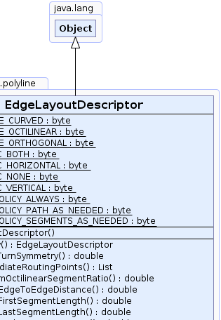
java.lang.Object
public class EdgeLayoutDescriptor
This class is used by EdgeRouter to provide routing details for the edges of the graph.
An EdgeLayoutDescriptor instance can be specified individually for single edges using a
DataProvider that returns an EdgeLayoutDescriptor instance for each edge of the graph, or
null if no EdgeLayoutDescriptor is bound to an edge. The DataProvider is
registered with the graph using key EdgeRouter.EDGE_LAYOUT_DESCRIPTOR_DPKEY.
This class is designed such that it allows future additions of new getter methods.
EdgeRouter.EDGE_LAYOUT_DESCRIPTOR_DPKEY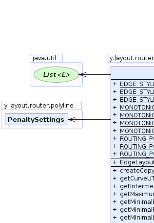 |
 |
 |
 |
| Field Summary | |
|---|---|
static byte |
EDGE_STYLE_CURVED
A routing style constant specifying that the edge should be curved. |
static byte |
EDGE_STYLE_OCTILINEAR
A routing style constant specifying that the edge should be octilinear. |
static byte |
EDGE_STYLE_ORTHOGONAL
A routing style constant specifying that the edge should be orthogonal. |
static byte |
MONOTONIC_BOTH
A constant specifying monotonic edge path restrictions for the horizontal and vertical direction. |
static byte |
MONOTONIC_HORIZONTAL
A constant specifying monotonic edge path restrictions for the horizontal direction. |
static byte |
MONOTONIC_NONE
A constant specifying that there are no monotonic edge path restrictions. |
static byte |
MONOTONIC_VERTICAL
A constant specifying monotonic edge path restrictions for the vertical direction. |
static byte |
ROUTING_POLICY_ALWAYS
A routing policy that indicates that a new route is calculated in any case. |
static byte |
ROUTING_POLICY_PATH_AS_NEEDED
A routing policy that indicates that based on the current path it is automatically determined whether an edge is routed, and if so, the edge gets a whole new path. |
static byte |
ROUTING_POLICY_SEGMENTS_AS_NEEDED
A routing policy that indicates that based on the current path it is automatically determined whether the edge is routed, and if so, only the necessary segments are changed. |
| Constructor Summary | |
|---|---|
EdgeLayoutDescriptor()
Creates a new instance of an EdgeLayoutDescriptor with the default settings. |
|
| Method Summary | |
|---|---|
EdgeLayoutDescriptor |
createCopy()
Creates a copy of this EdgeLayoutDescriptor instance. |
double |
getCurveUTurnSymmetry()
Returns how symmetric u-turn parts of curved routes should preferably be. |
java.util.List |
getIntermediateRoutingPoints()
Returns the list of intermediate YPoints that need to lie on the edge route. |
double |
getMaximumOctilinearSegmentRatio()
Specifies the maximum ratio between the horizontal/vertical part of a segment and the non-orthogonal, octilinear part. |
double |
getMinimalEdgeToEdgeDistance()
Returns the minimum distance between a pair of edges. |
double |
getMinimalFirstSegmentLength()
Returns the minimum length of the first segment of the edge path (at the source node). |
double |
getMinimalLastSegmentLength()
Returns the minimum length of the last segment of the edge path (at the target node). |
double |
getMinimalNodeCornerDistance()
Returns the minimum distance that the edge should maintain from node corners when entering or leaving the node. |
byte |
getMonotonicPathRestriction()
Returns the monotonic path restrictions that should be applied. |
PenaltySettings |
getPenaltySettings()
Returns the PenaltySettings used for this edge. |
double |
getPreferredOctilinearSegmentLength()
Returns the preferred length of non-orthogonal, octilinear segments. |
byte |
getRoutingPolicy()
Returns the routing policy indicating if the edge associated with this descriptor is unconditionally routed or if the existing route determines whether a routing is even necessary. |
byte |
getRoutingStyle()
Returns the routing style for the edge associated with this descriptor. |
byte |
getSourceCurveConnectionStyle()
Returns the style which determines how curved edge paths connect at the source side of the edge. |
byte |
getTargetCurveConnectionStyle()
Returns the style using which determines how edge paths connect at the target side of the edge. |
boolean |
isControlPointCreationEnabled()
Returns whether or not the points of the resulting edge path represent cubic bezier control points. |
boolean |
isCurveShortcutsAllowed()
Returns whether or not curved edges may shortcut and introduce
additional edge crossings to make curves more direct and smoother. |
boolean |
isDirectGroupContentEdgeRoutingEnabled()
Returns whether or not this edge is routed directly to a group node's border if it connects the group node with one of its descendants. |
void |
setControlPointCreationEnabled(boolean controlPointCreation)
Specifies whether or not the points of the resulting edge path represent cubic bezier control points. |
void |
setCurveShortcutsAllowed(boolean curveShortcutsAllowed)
Specifies whether or not curved edges may shortcut and introduce
additional edge crossings to make curves more direct and smoother. |
void |
setCurveUTurnSymmetry(double curveUTurnSymmetry)
Specifies how symmetric u-turn parts of curved routes should preferably be. |
void |
setDirectGroupContentEdgeRoutingEnabled(boolean enabled)
Specifies whether or not this edge is routed directly to a group node's border if it connects the group node with one of its descendants. |
void |
setIntermediateRoutingPoints(java.util.List intermediateRoutingPoints)
Specifies the list of intermediate YPoints that need to lie on the edge route. |
void |
setMaximumOctilinearSegmentRatio(double maximumRatio)
Specifies the maximum ratio between the horizontal/vertical part of a segment and the non-orthogonal, octilinear part. |
void |
setMinimalEdgeToEdgeDistance(double distance)
Specifies the minimum distance between a pair of edges. |
void |
setMinimalFirstSegmentLength(double length)
Specifies the minimum length of the first segment of the edge path (at the source node). |
void |
setMinimalLastSegmentLength(double length)
Specifies the minimum length of the last segment of the edge path (at the target node). |
void |
setMinimalNodeCornerDistance(double distance)
Specifies the minimum distance that the edge should maintain from node corners when entering or leaving the node. |
void |
setMonotonicPathRestriction(byte restriction)
Specifies the monotonic path restrictions that should be applied. |
void |
setPenaltySettings(PenaltySettings penaltySettings)
Specifies the PenaltySettings used for this edge. |
void |
setPreferredOctilinearSegmentLength(double preferredLength)
Specifies the preferred length of non-orthogonal, octilinear segments. |
void |
setRoutingPolicy(byte routingPolicy)
Specifies the routing policy indicating if the edge associated with this descriptor is unconditionally routed or if the existing route determines whether a routing is even necessary. |
void |
setRoutingStyle(byte routingStyle)
Specifies the routing style for the edge associated with this descriptor. |
void |
setSourceCurveConnectionStyle(byte curveConnectionStyle)
Specifies the style which determines how curved edge paths connect at the source side of the edge. |
void |
setTargetCurveConnectionStyle(byte curveConnectionStyle)
Specifies the style which determines how curved edge paths connect at the target side of the edge. |
| Methods inherited from class java.lang.Object |
|---|
clone, equals, finalize, getClass, hashCode, notify, notifyAll, toString, wait, wait, wait |
| Field Detail |
|---|
public static final byte ROUTING_POLICY_ALWAYS
The existing path of an edge is ignored and the routing algorithm unconditionally generates a whole new path.
 Initial graph | 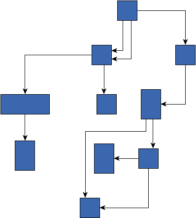 The edges got a new path, ignoring the existing one |
public static final byte ROUTING_POLICY_PATH_AS_NEEDED
The automatic selection examines the existing, given path of an edge. Based on various criteria it heuristically determines whether or not it needs to be routed. For example, intersections with other elements or a routing style violation are clear indicators. A further criterion is when the port constraints/candidates are not properly satisfied. Edges deemed to be 'good' are not changed.
This policy is convenient for cases where it is not clear which edges the algorithm should route. For example, after a user interaction (moving a node, inserting new elements etc.), routing of edges might become necessary but depending on the action it can not definitely be said which edges need to be corrected.
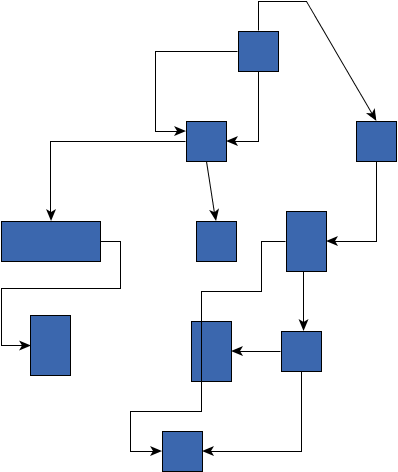 Initial graph |  The three edges were selected for routing and they got a completely new path |
public static final byte ROUTING_POLICY_SEGMENTS_AS_NEEDED
This policy follows the same approach as ROUTING_POLICY_PATH_AS_NEEDED for determining whether or
not an edge is even routed. However, during routing, the changes are kept local. This means that
only certain segments are changed, keeping the rest of the route, wherever appropriate.
Edges deemed to be 'good' are not changed at all.
This policy is convenient for cases where it is not clear which edges the algorithm should route. For example, after a user interaction (moving a node, inserting new elements etc.), routing of edges might become necessary but depending on the action it can not definitely be said which edges need to be corrected.
curved edges, this policy is equal to
ROUTING_POLICY_PATH_AS_NEEDED, meaning that if necessary the whole curved edge will be routed. Initial graph | 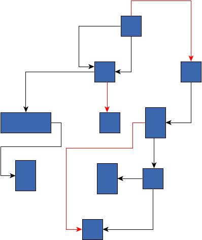 The three edges were selected for routing but only changed locally, keeping some existing segments |
public static final byte EDGE_STYLE_ORTHOGONAL
 Routing style orthogonal |
public static final byte EDGE_STYLE_OCTILINEAR
-1 and 1.
bus are always routed orthogonally.
Bus connections that lead from the backbone to the actual end nodes can be octilinear.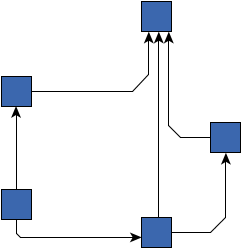 Routing style octilinear |
public static final byte EDGE_STYLE_CURVED
Curved edges are constructed using cubic bezier splines. As for all routing styles, overlaps with other elements are avoided. If there is very little space for a smooth curve, it can happen that the resulting path remains orthogonal. Therefore, the curved routing style does not produce optimal results for input graphs that offer little space for the edge routes.
When integrated edge labeling is enabled, for edge
labels a straight, non-curved segment where the label is placed will be inserted.
All the settings of the PreferredPlacementDescriptor are supported.
Similarly, for the minimum first segment length
and the minimum last segment length, a straight
edge segment is created to fulfill the constraints.
setControlPointCreationEnabled(boolean) Routing style curved |
public static final byte MONOTONIC_NONE
The direction of the edge segments is not restricted, hence, intermediate segments might also point in a direction other than the one towards the target.
setMonotonicPathRestriction(byte),
Constant Field Valuespublic static final byte MONOTONIC_VERTICAL
This implies that each vertical edge segment is directed from the source to the target. Note that if the source and target node are located on the same y-coordinate, then this restriction can not have an effect.
setMonotonicPathRestriction(byte),
Constant Field Valuespublic static final byte MONOTONIC_HORIZONTAL
This implies that each horizontal edge segment is directed from the source to the target. Note that if the source and target node are located on the same x-coordinate, then this restriction can not have an effect.
setMonotonicPathRestriction(byte),
Constant Field Valuespublic static final byte MONOTONIC_BOTH
This implies that each horizontal as well as each vertical edge segment is directed from the source to the target.
setMonotonicPathRestriction(byte),
Constant Field Values| Constructor Detail |
|---|
public EdgeLayoutDescriptor()
EdgeLayoutDescriptor with the default settings.
| Method Detail |
|---|
public void setMinimalFirstSegmentLength(double length)
The minimum length should be greater than or equal to 0. If a negative value is given as input,
the default value, i.e., 5.0, will be used instead.
Grid.getSpacing()).
If the grid is larger than the specified minimum length, then the grid size defines the actual minimum.CurveConnectionStyle.ORGANIC.length - the minimum length of the first segment Minimum first segment length 10 | 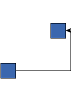 Minimum first segment length 100 |
public double getMinimalFirstSegmentLength()
The minimum length should be greater than or equal to 0. If a negative value is given as input,
the default value, i.e., 5.0, will be used instead.
Grid.getSpacing()).
If the grid is larger than the specified minimum length, then the grid size defines the actual minimum.CurveConnectionStyle.ORGANIC.setMinimalFirstSegmentLength(double)public void setMinimalLastSegmentLength(double length)
The minimum length should be greater than or equal to 0. If a negative value is given as input,
the default value, i.e., 10.0, will be used instead.
Grid.getSpacing()).
If the grid is larger than the specified minimum length, then the grid size defines the actual minimum.CurveConnectionStyle.ORGANIC.length - the minimum length of the last segment Minimum last segment length 10 | 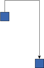 Minimum last segment length 200 |
public double getMinimalLastSegmentLength()
The minimum length should be greater than or equal to 0. If a negative value is given as input,
the default value, i.e., 10.0, will be used instead.
Grid.getSpacing()).
If the grid is larger than the specified minimum length, then the grid size defines the actual minimum.CurveConnectionStyle.ORGANIC.setMinimalLastSegmentLength(double)public double getMinimalEdgeToEdgeDistance()
The minimum distance should be greater than or equal to 0. If a negative value is given as input,
the default value, i.e., 3.0, will be used instead.
setMinimalEdgeToEdgeDistance(double)public void setMinimalEdgeToEdgeDistance(double distance)
The minimum distance should be greater than or equal to 0. If a negative value is given as input,
the default value, i.e., 3.0, will be used instead.
distance - the minimum distance between a pair of edges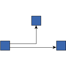 Minimum edge to edge distance 3.0 | 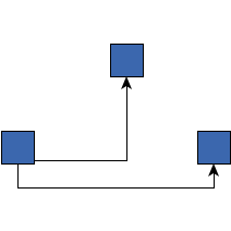 Minimum edge to edge distance 25.0 |
public double getMinimalNodeCornerDistance()
The minimum distance should be greater than or equal to 0. If a negative value is given as input,
the default value, i.e., 3.0, will be used instead.
setMinimalNodeCornerDistance(double)public void setMinimalNodeCornerDistance(double distance)
The minimum distance should be greater than or equal to 0. If a negative value is given as input,
the default value, i.e., 3.0, will be used instead.
distance - the minimum distance the edge should maintain from node corners Minimum node corner distance 3.0 |  Minimum node corner distance 10.0 |
public byte getMonotonicPathRestriction()
Monotonic path restrictions imply that (ideally) the vertical and/or horizontal segments of an edge path are directed from the source node towards the target node without ever changing their direction back towards the source node.
If an unknown restriction is specified, MONOTONIC_NONE will be used instead.
setMonotonicPathRestriction(byte)public void setMonotonicPathRestriction(byte restriction)
Monotonic path restrictions imply that (ideally) the vertical and/or horizontal segments of an edge path are directed from the source node towards the target node without ever changing their direction back towards the source node.
If an unknown restriction is specified, MONOTONIC_NONE will be used instead.
MONOTONIC_NONE. No path restrictions are used.restriction - one of the predefined monotonic path restrictionspublic byte getRoutingStyle()
setRoutingStyle(byte)public void setRoutingStyle(byte routingStyle)
EDGE_STYLE_ORTHOGONALroutingStyle - one of the predefined routing styles
java.lang.IllegalArgumentException - if an unknown routing style is givenpublic byte getRoutingPolicy()
setRoutingPolicy(byte)public void setRoutingPolicy(byte routingPolicy)
ROUTING_POLICY_ALWAYS. The edge is routed, ignoring the existing sketch.routingPolicy - one of the predefined routing policies
java.lang.IllegalArgumentException - if an unknown routing policy is givenpublic PenaltySettings getPenaltySettings()
PenaltySettings used for this edge.
Besides specifying a completely customized setting, the user can choose
between four predefined optimization strategies: PenaltySettings.OPTIMIZATION_BALANCED,
PenaltySettings.OPTIMIZATION_EDGE_BENDS, PenaltySettings.OPTIMIZATION_EDGE_CROSSINGS
and PenaltySettings.OPTIMIZATION_EDGE_LENGTHS.
PenaltySettings.OPTIMIZATION_BALANCED,
PenaltySettings.OPTIMIZATION_EDGE_BENDS,
PenaltySettings.OPTIMIZATION_EDGE_CROSSINGS,
PenaltySettings.OPTIMIZATION_EDGE_LENGTHSpublic void setPenaltySettings(PenaltySettings penaltySettings)
PenaltySettings used for this edge.
Besides specifying a completely customized setting, the user can choose
between four predefined optimization strategies: PenaltySettings.OPTIMIZATION_BALANCED,
PenaltySettings.OPTIMIZATION_EDGE_BENDS, PenaltySettings.OPTIMIZATION_EDGE_CROSSINGS
and PenaltySettings.OPTIMIZATION_EDGE_LENGTHS.
penaltySettings - the penalty settings used for this edge
java.lang.IllegalArgumentException - if the given penalty settings are nullPenaltySettings.OPTIMIZATION_BALANCED,
PenaltySettings.OPTIMIZATION_EDGE_BENDS,
PenaltySettings.OPTIMIZATION_EDGE_CROSSINGS,
PenaltySettings.OPTIMIZATION_EDGE_LENGTHSpublic boolean isDirectGroupContentEdgeRoutingEnabled()
When enabled, the edge will connect to the inner side of the group node's border instead of leaving the group node and connect from outside.
PortCandidates as well as PortConstraints are supported for direct content
edges, including fixed PortCandidates and strong
PortConstraints. Note that, for example, a constraint with direction
PortConstraint.NORTH at the side of the enclosing group node means that the edge connects
to the upper group node border from inside and never leaves the group node.
BusDescriptor,
see EdgeRouter.BUS_DESCRIPTOR_DPKEY.true if the edge is routed directly, false otherwisesetDirectGroupContentEdgeRoutingEnabled(boolean)public void setDirectGroupContentEdgeRoutingEnabled(boolean enabled)
When enabled, the edge will connect to the inner side of the group node's border instead of leaving the group node and connect from outside.
PortCandidates as well as PortConstraints are supported for direct content
edges, including fixed PortCandidates and strong
PortConstraints. Note that, for example, a constraint with direction
PortConstraint.NORTH at the side of the enclosing group node means that the edge connects
to the upper group node border from inside and never leaves the group node.
BusDescriptor,
see EdgeRouter.BUS_DESCRIPTOR_DPKEY.enabled - true if the edge is routed directly, false otherwise false |  true |
public java.util.List getIntermediateRoutingPoints()
YPoints that need to lie on the edge route.
The edge route is constructed such that all the specified intermediate points lie on the route in the order they are specified. The route can, but must not necessarily bend at the specified points.
BusDescriptor, see EdgeRouter.BUS_DESCRIPTOR_DPKEY.YPoints representing intermediate routing points,
or null if there are no intermediate pointssetIntermediateRoutingPoints(List),
EdgeRouter.BUS_DESCRIPTOR_DPKEYpublic void setIntermediateRoutingPoints(java.util.List intermediateRoutingPoints)
YPoints that need to lie on the edge route.
The edge route is constructed such that all the specified intermediate points lie on the route in the order they are specified. The route can, but must not necessarily bend at the specified points.
BusDescriptor, see EdgeRouter.BUS_DESCRIPTOR_DPKEY.intermediateRoutingPoints - the list of YPoints representing intermediate routing points,
or null if there should be no intermediate pointsEdgeRouter.BUS_DESCRIPTOR_DPKEYpublic boolean isControlPointCreationEnabled()
true if the bends are interpreted as cubic bezier control points, false otherwisesetControlPointCreationEnabled(boolean)public void setControlPointCreationEnabled(boolean controlPointCreation)
controlPointCreation - true if the points of the edge path should represent cubic
bezier control points, false otherwisepublic boolean isCurveShortcutsAllowed()
curved edges may shortcut and introduce
additional edge crossings to make curves more direct and smoother.
In relation to nodes, labels and other edges, the curved and non-curved edges take the same route, for example, both might cross a certain other edge or pass a certain node on its left side. If this property is disabled (default), the curved edges adhere to this.
If enabled, however, curved edges may shortcut and cross additional edges. This can yield to a direct and possibly smoother curved route. Still, intersections with nodes, node labels and edge labels are not allowed.
curved edge routing style.
It is not possible to precisely predict the impact of this setting for the general case.true, if curved edges may shortcut in favor of more direct curves,
false, otherwiseEDGE_STYLE_CURVEDpublic void setCurveShortcutsAllowed(boolean curveShortcutsAllowed)
curved edges may shortcut and introduce
additional edge crossings to make curves more direct and smoother.
In relation to nodes, labels and other edges, the curved and non-curved edges take the same route, for example, both might cross a certain other edge or pass a certain node on its left side. If this property is disabled (default), the curved edges adhere to this.
If enabled, however, curved edges may shortcut and cross additional edges. This can yield to a direct and possibly smoother curved route. Still, intersections with nodes, node labels and edge labels are not allowed.
curved edge routing style.
It is not possible to precisely predict the impact of this setting for the general case.curveShortcutsAllowed - true, if curved edges may shortcut in favor
of more direct curves, false, otherwiseisCurveShortcutsAllowed(),
EDGE_STYLE_CURVED Curve shortcuts are disabled | 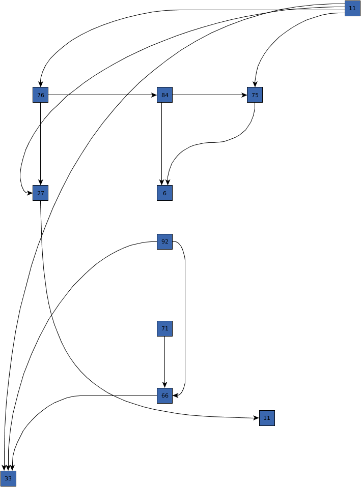 Curve shortcuts are enabled |
public double getCurveUTurnSymmetry()
curved routes should preferably be.
If this property is greater than zero, the algorithm tries to achieve a more symmetric path for
180-degree turns (u-turns) by specifically handling them. Symmetric turns likely require more space compared
to more direct variants.
The value of this property must be within interval [0,1], where a higher value indicates
more emphasis on symmetry and lower values that symmetry is not important.
This setting influences the symmetry of a single curved route and does not affect symmetry of multiple curves in relation to each other.
0 might be perceived as being greater than the difference
between other values. The reason is that with 0, u-turns are not handled specifically at all.curved edge routing style.[0,1], where a higher value means that symmetric turns are preferredEDGE_STYLE_CURVED,
setCurveUTurnSymmetry(double)public void setCurveUTurnSymmetry(double curveUTurnSymmetry)
curved routes should preferably be.
If this property is greater than zero, the algorithm tries to achieve a more symmetric path for
180-degree turns (u-turns) by specifically handling them. Symmetric turns likely require more space compared
to more direct variants.
The value of this property must be within interval [0,1], where a higher value indicates
more emphasis on symmetry and lower values that symmetry is not important.
This setting influences the symmetry of a single curved route and does not affect symmetry of multiple curves in relation to each other.
0 might be perceived as being greater than the difference
between other values. The reason is that with 0, u-turns are not handled specifically at all.curved edge routing style.curveUTurnSymmetry - the symmetry preference for u-turns of curved edges within interval
[0,1], where a higher value means that symmetric turns are preferred
java.lang.IllegalArgumentException - if the given symmetry value is negative or larger than oneEDGE_STYLE_CURVED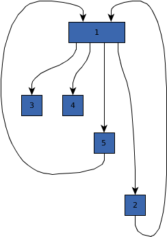 0.0 | 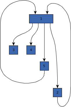 0.7 | 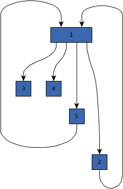 1.0 |
public byte getSourceCurveConnectionStyle()
setTargetCurveConnectionStyle(byte),
setSourceCurveConnectionStyle(byte)public void setSourceCurveConnectionStyle(byte curveConnectionStyle)
curveConnectionStyle - one of the predefined curve connection styles
java.lang.IllegalArgumentException - if an unknown connection style is givensetTargetCurveConnectionStyle(byte) CurveConnectionStyle.KEEP_PORT setting at source and target side - normal ports by the routing algorithm | 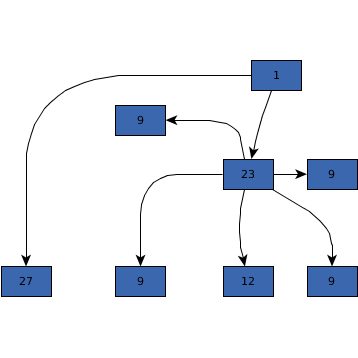 CurveConnectionStyle.ORGANIC setting at source and target side - more organic ports and more direct curves |
public byte getTargetCurveConnectionStyle()
setSourceCurveConnectionStyle(byte),
setTargetCurveConnectionStyle(byte)public void setTargetCurveConnectionStyle(byte curveConnectionStyle)
curveConnectionStyle - one of the predefined curve connection styles
java.lang.IllegalArgumentException - if an unknown connection style is givensetSourceCurveConnectionStyle(byte)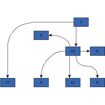 CurveConnectionStyle.KEEP_PORT setting at source and target side - normal ports by the routing algorithm |  CurveConnectionStyle.ORGANIC setting at source and target side - more organic ports and more direct curves |
public double getPreferredOctilinearSegmentLength()
If there is not enough space to use this preferred length, the segments may also be shorter.
The preferred length of non-orthogonal, octilinear segments has to be greater than or equal to 0.
octilinear routing.setPreferredOctilinearSegmentLength(double),
EDGE_STYLE_OCTILINEAR,
setMaximumOctilinearSegmentRatio(double)public void setPreferredOctilinearSegmentLength(double preferredLength)
If there is not enough space to use this preferred length, the segments may also be shorter.
The preferred length of non-orthogonal, octilinear segments has to be greater than or equal to 0.
octilinear routing.preferredLength - the preferred length of non-orthogonal, octilinear segments
java.lang.IllegalArgumentException - if the preferred octilinear segment length is negativeEDGE_STYLE_OCTILINEAR,
setMaximumOctilinearSegmentRatio(double) Preferred octilinear segment length 10 | 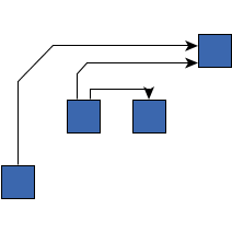 Preferred octilinear segment length 50 |
public double getMaximumOctilinearSegmentRatio()
When octilinear segments are added to an edge path, corners between horizontal and vertical segments are cut and
replaced by the new segment. This ratio describes the cutting points on a segment. If it is zero, the route stays
orthogonal. The value cannot be larger than 0.5 because there may be another non-orthogonal segment
at the other side of the segment. For long orthogonal segments the length of the octilinear segment is
determined by the value of property getPreferredOctilinearSegmentLength().
The maximum octilinear segment ratio must be between 0 and 0.5.
octilinear routing.setMaximumOctilinearSegmentRatio(double),
EDGE_STYLE_OCTILINEAR,
setPreferredOctilinearSegmentLength(double)public void setMaximumOctilinearSegmentRatio(double maximumRatio)
When octilinear segments are added to an edge path, corners between horizontal and vertical segments are cut and
replaced by the new segment. This ratio describes the cutting points on a segment. If it is zero, the route stays
orthogonal. The value cannot be larger than 0.5 because there may be another non-orthogonal segment
at the other side of the segment. For long orthogonal segments the length of the octilinear segment is
determined by the value of property getPreferredOctilinearSegmentLength().
The maximum octilinear segment ratio must be between 0 and 0.5.
octilinear routing.maximumRatio - the maximum octilinear segment ratio
java.lang.IllegalArgumentException - if the maximum ratio is negative or greater than 0.5EDGE_STYLE_OCTILINEAR,
setPreferredOctilinearSegmentLength(double) Ratio 0.3, the octilinear parts from left and right both cover a third of the horizontal distance |  Ratio 0.5, the octilinear parts from left and right both cover half of the horizontal distance |
public EdgeLayoutDescriptor createCopy()
EdgeLayoutDescriptor instance.
EdgeLayoutDescriptor instance
|
© Copyright 2000-2025, yWorks GmbH. All rights reserved. |
||||||||
| PREV CLASS NEXT CLASS | FRAMES NO FRAMES | ||||||||
| SUMMARY: NESTED | FIELD | CONSTR | METHOD | DETAIL: FIELD | CONSTR | METHOD | ||||||||