| Radial Layout Style | ||
|---|---|---|
| Prev | Chapter 5. Automatic Graph Layout | Next |
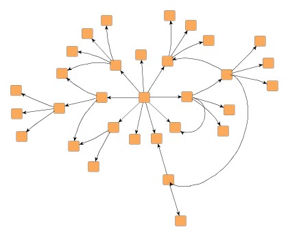
This section presents the radial layout style.
In the radial layout style, the nodes of a graph are arranged on concentric circles. The layout calculation starts by conceptually reducing the graph to a tree structure whose root node is taken as the center of all circles. Each child node in this tree structure is then placed on the next outer circle within the sector of the circle that was reserved by its parent node. All edges that were initially ignored are re-established and the radii of the circles are calculated taking the sector sizes needed by each whole subtree into account.
This layout style is well suited for the visualization of directed graphs and tree-like structures.
Class RadialLayouter![]() is a layout
provider of radial layout.
is a layout
provider of radial layout.
Class RadialLayouter provides a set of options that affect its layout
behavior.
These options can be set using the properties of class RadialLayouter.
The options are documented within the API documentation of class
RadialLayouter![]() .
.
The policy to choose the center node from the node set of the graph can be determined
by using the
centerNodesPolicy![]() property.
The following policies are available:
property.
The following policies are available:
CENTER_NODES_POLICY_DIRECTED |
|
| Description | Chooses the center node from the set of nodes that have no predecessors. If this set is empty, an arbitrary node of the graph becomes the center node. |
CENTER_NODES_POLICY_CENTRALITY |
|
| Description | The node that has the highest centrality becomes the center node. |
CENTER_NODES_POLICY_WEIGHTED_CENTRALITY |
|
| Description | The node that has the highest weighted centrality becomes the center node. This is the default setting. |
CENTER_NODES_POLICY_SELECTED_NODES |
|
| Description |
Uses a custom selection of nodes.
To specify the nodes, a data provider holding the selection information for each
node is looked up.
The data provider is expected to be registered with the graph using the look-up
key returned by centerNodesDpKey |
The layeringStrategy![]() property specifies how nodes will be distributed to the layers.
These layering strategies are available:
property specifies how nodes will be distributed to the layers.
These layering strategies are available:
LAYERING_STRATEGY_BFS |
|
| Description | Layering based on a breadth-first search (BFS). All edges will span at most one layer in the resulting drawing. Edges between nodes that belong to the same layer are possible. This is the default setting. |
LAYERING_STRATEGY_HIERARCHICAL |
|
| Description | The layer distance of an edge is the absolute difference between the layer numbers of its source and target node. Layer assignment will be done in such a way that the overall sum of the layer distances of all edges in the layout is minimal. |
The distance between the layers depends on the space that is needed by the subtrees. However, the layer spacing can be controlled and a minimal distance can be defined.
| Layer Spacing | |
| API | layerSpacing:Number |
| Description | Defines a unit value for the distance between circles, i.e., each circle radius is a multiple of this value. |
| Minimal Layer Distance | |
| API | minimalLayerDistance:Number |
| Description | Defines the minimal layer distance. |
Edge routing options include different routing policies that can be specified using
the edgeRoutingStrategy![]() property:
property:
EDGE_ROUTING_STRATEGY_POLYLINE |
|
| Description | Polyline edge routing. Edges will be routed straight-line, if possible, or have bends on the circles. |
EDGE_ROUTING_STRATEGY_ARC |
|
| Description | Arc edge routing. Source and target of an edge as well as one bend on each spanned circle are used as main control points. Additional control points are inserted in-between to create an arc-like edge. This is the default setting. |
Note that with both edge routing policies overlaps of edge paths with nodes cannot always be prevented. In particular, this affects edges that span multiple circles (i.e., layers).
RadialLayouter by default supports node halos as soon as they are declared. It considers any specified additional paddings around nodes, however, edges can cross through these areas in the resulting diagram.
The following table lists the data provider look-up keys that are recognized by RadialLayouter in conjunction with node halo support.
Table 5.61. Data provider look-up keys
| Key | Element Type | Value Type | Description |
|---|---|---|---|
| NODE_HALO_DPKEY |
node | NodeHalo |
A NodeHalo |
Class RadialLayouter knows a number of data provider keys which are used to retrieve supplemental layout data for a graph's elements. The data is bound to the graph by means of a data provider, which is registered using a given look-up key. Table 5.62, “Data provider look-up keys” lists all look-up keys for RadialLayouter.
Binding supplemental layout data to a graph is described in the section called “Providing Supplemental Layout Data”.
Table 5.62. Data provider look-up keys
| Key | Element Type | Value Type | Description |
|---|---|---|---|
| NODE_HALO_DPKEY |
node | NodeHalo |
A NodeHalo |
|
Copyright ©2010-2015, yWorks GmbH. All rights reserved. |